Maximum 057-1655-2 Manual de usuario


3
TABLE OF CONTENTS
NOTE: If any parts are missing or damaged, or if you have any
questions, please call our toll-free helpline at 1-888-670-6682.
SAVE THESE INSTRUCTIONS
This manual contains important safety and
operating instructions. Read all instructions and
follow them when using this product.
TABLE OF CONTENTS
Specifications
Safety guidelines
Assembly
Operation
Exploded view
Parts list
Warranty
4
5
7
15
22
23
24

5
SAFETY GUIDELINES
4
SPECIFICATIONS
Material
Maximum height
Maximum load
Weight
Steel tube construction
23 1/4" (59 cm) from ground to stand top
132 lb (60 kg)
31 lb 11 oz (14.4 kg)
SPECIFICATIONS SAFETY GUIDELINES
This manual contains information that relates to PROTECTING PERSONAL SAFETY and
PREVENTING EQUIPMENT PROBLEMS. It is very important to read this manual carefully
and understand it thoroughly before using the product. The symbols listed below are
used to indicate this information.
WARNING!
•Read and understand all instructions. Failure to follow all
instructions may result in serious personal injury.
DANGER!
Potential hazard that will result in serious injury or loss of life.
WARNING!
Potential hazard that could result in serious injury or loss of life.
CAUTION!
Potential hazard that may result in moderate injury or damage to equipment.
Note: The word “Note” is used to inform the reader of something the operator needs to
know about the tool.
SAFETY RECOMMENDATIONS
These precautions are intended for the personal safety of the operator and others
working with the operator. Failure to follow these instructions may result in a permanent
loss of vision, serious personal or even fatal injury, property damage and/or tool damage.
Please take time to read and understand these instructions.
Safety is a combination of common sense, staying alert and knowing how your table saw
works.
SAFETY RULES FOR THE STAND
•Fully assemble and tighten all the fasteners required for this stand. Also remember to
occasionally check the stand and make sure all fasteners are still tight. A loose stand is
unstable and may shift in use and cause serious injury.
•Turn tool switch off and disconnect power before mounting it to the stand. Unintended
startup during assembly can cause injury.
•Assemble only according to these instructions. Improper assembly can create hazards.
•Wear ANSI-approved safety goggles and heavy-duty work gloves during assembly.
•Keep assembly area clean and well lit.
•Keep bystanders out of the area during assembly.
•Do not assemble when tired or when under the infuence of drugs or medication.
•Follow all warnings and instructions in the manual.
model no. 057-1655-2 | contact us 1-888-670-6682

7
ASSEMBLY
6
SAFETY GUIDELINES
•Ensure the weight of the tool is centred and mounted correctly before operating.
•Before operating the tool, make sure the entire unit is placed on a solid, flat, level
surface. Serious injury could occur if tool is unstable and tips.
•Ensure that all power tools and electrical cords are properly grounded and in working
order.
•Never stand on tool or its stand or use as ladder or scaffolding. Serious injury could
occur if the stand is tipped or the cutting tool is accidentally contacted. Do not store
materials on or near the stand such that it is necessary to stand on the tool or its stand
to reach them.
•DO NOT exceed maximum weight capacity of the stand.
•This product is not a toy. Do not allow children to play with or near this item.
•Maintain product labels and nameplates. These carry important safety information.
•Use only identical replacement parts. Any others may create a hazard.
PACKAGE CONTENTS
No. Description Qty Illustration
Stand assembly
Stand support
Handle assembly
Support A
Support B
Levelling footing assembly and locking
knob
Hex bolt M8 x 60, flat washer 8, shock
absorption pad and locking knob
Flat round head screws M6 x45 and
locking nuts M6
1
2
3
4
5
6
7
8
1
1
1
2
2
1
1
2
model no. 057-1655-2 | contact us 1-888-670-6682

9
model no. 057-1655-2 | contact us 1-888-670-6682
ASSEMBLY
8
ASSEMBLY
No. Description Qty Illustration
Roller wheels, roller sleeves, big flat
washer 8, big flat washer 10 and
locking nuts M8
Flat round head screws M8 x 45 and
locking nuts M8 (used for handle
assembly)
Flat round head screws M8 x 45 and
hex nuts M8 (used for support A)
Flat round head screws M8 x 45 (used
for support B)
Flat round head screws M6 x 45, big flat
washer 6 and locking nuts M6 (attach
Dewalt/Bosch table saw to stand)
Flat round head screws M8 x 75, flat
washers 8 and locking nuts M8 (attach
055-6766-2 MAXIMUM™ 10" (25.4 cm)
Compact Table Saw to stand)
4 mm, 5 mm hex key
9
10
11
12
13
14
15
2
2
4
4
4
4
2
Fig. 1
ASSEMBLE THE LEG STAND (Fig. 1-4)
Group the leg stand parts by type and size. Refer to the package contents.
ATTACH STAND SUPPORT (Fig. 1)
•Place the stand assembly (1) on a flat surface.
•Attach the tubes of the stand support (2) with the corresponding tubes of the stand
assembly (1) and align the holes.
•Insert the flat round head screw M8 x 75 (3) on the levelling foot (4) assembly into the
hole (with a hex nut M8 welded on it) and tighten the screw (3) with 5 mm hex key
(supplied).
•Secure the locking knob (5) by turning it clockwise.
•Secure the shock absorption pad (6) with a hex bolt M8 x 60 (7) and a flat washer 8 (8)
on the other hole with adjustable wrench (not supplied).
•Tighten the locking knob (9) clockwise.
•Insert the flat round head screws M6 x 45 (10) on other two holes, then tighten two
locking nuts M6 (11) and flat round head screws M6 x 45 (10).
9
10
11
8
6
7
2
4
3
5
10
11
1
model no. 057-1655-2 | contact us 1-888-670-6682

11
ASSEMBLY
10
ASSEMBLY
Fig. 4 shows the complete open leg stand assembly.
Fig. 2
Fig. 3
Fig. 4
ATTACH HANDLE ASSEMBLY (Fig. 2)
•Attach the tubes of the handle assembly (1) with the corresponding tubes of the stand
assembly (2) and align the holes.
•Insert a flat round head screw M8 x 45 (3) through the hole and tighten with a locking
nut M8 (4).
•Repeat the second procedure on other hole.
ATTACH ROLLER WHEELS (Fig. 3)
•Slide a big flat washer M10 (1), roller sleeve (2), roller wheel (3), a big flat washer M8 (4)
and a locking nut M8 (5) on the axle (6) through the hole in the centre of the roller
wheel (2).
•Secure in place using the adjustable wrench (not supplied).
•Repeat with the second roller wheel (2).
1
2
4
2
3
4
1
6
1
2
3
4
5
model no. 057-1655-2 | contact us 1-888-670-6682

13
ASSEMBLY
12
ASSEMBLY
Fig. 6
ASSEMBLE THE SUPPORT A OR B (FIG. 5-7)
This leg stand includes two support A and B to apply to four table saws (Support A:
Dewalt DW7480/DW745; Support B: Bosch GTS1031 and MAXIMUM™ 10" (25.4 cm)
Compact Table Saw 055-6766-2 ). You can select support A or B according to your
table saw.
Make sure that do not assemble the support A and B at the same time.
TO ASSEMBLE THE SUPPORT A (FIG. 5)
•Align the holes on the support A (1) with two sides of the tubes of the frame (2).
•Horizontally insert a flat round head screw M8 x 45 (3) through the hole and tighten
with a hex nut M8 (4) with 5 mm hex key (supplied).
•Repeat with other three holes.
TO ASSEMBLE THE SUPPORT B (FIG. 6 & 7)
Make sure that the four fixing holes on the frame tube for MAXIMUM™ 10" (25.4 cm)
Compact Table Saw 055-6766-2 are different from Bosch GTS1031 table saw.
•Align the holes on the support B (1) (the second (2) and last (3) holes) with top surface
of the tubes of the frame (4).
•Vertically insert a flat round head screw M8 x 45 (5) through the hole and tighten it
with 5 mm hex key (supplied).
•Repeat with other three holes.
Four holes a: MAXIMUM™ 10" (25.4 cm) Compact Table Saw 055-6766-2
Four holes b: Bosch GTS1031 table saw
Fig. 5
4
2
2
1
3
5
1
2
3
4
model no. 057-1655-2 | contact us 1-888-670-6682
15
OPERATION
14
ASSEMBLY
Fig. 8
Fig. 7
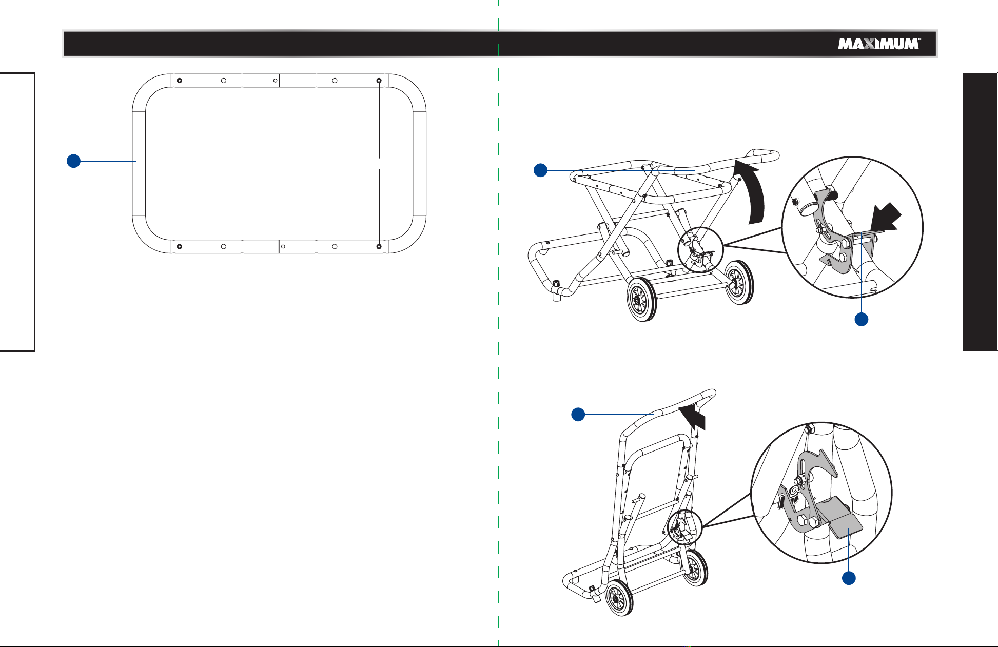
TO CLOSE THE LEG STAND (Fig. 8-9)
Make sure that remove the workpiece and store the accessories such as rip fence, blade
guard. etc. when the table saw attached to the leg stand.
•At the same time, grasp the handle (1), step on the release lever (2), and lift up on the
handle away from the body .
•Continue push the leg stand to rotate it down until release lever (2) clicks and locks
into place.
a b b a
41Press
with foot
1
Fig. 9
1
2
2
2
model no. 057-1655-2 | contact us 1-888-670-6682

Fig. 12
TO MOVE THE LEG STAND (FIG. 10-11)
•Begin with the leg stand in the locked upright position.
•Grasp the handle (1) firmly, place one foot against axle bar (2) for leverage, and pull
handle back towards you so the leg stand is balanced on the roller wheels.
•Pull the leg stand to the desired location then either open the stand or store the leg
stand in a dry enviroment.
Fig. 10
Fig. 11
1716
OPERATION
OPERATION
TO OPEN THE LEG STAND (Fig. 12-13)
•Place the stand upright on floor in front of you, step on the release lever (1) and pull the
handle (2) toward you at the same time.
•Once the leg stand is released from the release lever, ease the stand toward the floor by
pushing the handle toward the floor.
•With your hands on the handle, push the leg stand towards the ground until the release
lever (1) closes over the centre brace (3), locking the leg stand in an open position.
Press
with foot
1
Place
one foot
1
2
1
2
2
1
Fig. 13
2
3
1
2
2
model no. 057-1655-2 | contact us 1-888-670-6682

Fig. 15
Fig. 16
TO ATTACH THE TABLE SAW TO LEG STAND (FIG. 14-18)
Make sure that the motor is placed in the handle side when attaching the table saw to
the leg stand to allow for opening or closing the leg stand easily.
•Place the stand on a level surface and level the stand to the floor.
TO MOUNT THE MAXIMUM™ 10" (25.4 cm) COMPACT TABLE SAW 055-6766-2 (Fig. 14-15)
•Place table saw on the leg stand aligning holes in the U frame tube of the table saw
and with holes on the leg stand.
•Insert flat round head screws M8 x 75 (1) (supplied) along with flat washers 8 (2)
(supplied) into the aligned holes.
•Tighten all four locking nuts M8 (3) (supplied) and flat round head screws M8 x 75 (1)
with 5 mm hex key (supplied) and adjustable wrench (not supplied).
Fig. 14
1918
OPERATION
OPERATION
TO MOUNT THE BOSCH GTS1031 OR DEWALT DW7480/DW745 TABLE SAW (FIG. 16-17)
•Place table saw on the leg stand aligning holes in the base of the table saw with holes
on the leg stand.
•Insert flat round head screws M6 x 45 (supplied) along with big flat washers 6
(supplied) into the aligned holes.
•Tighten all four locking nuts M6 (supplied) and flat round head screws M6 x 45 with
4 mm hex key (supplied) and adjustable wrench (not supplied).
a: Mounting holes for MAXIMUM™ 10" (25.4 cm) Compact Table Saw 055-6766-2
b: Mounting holes for Bosch GTS1031 table saw
1
2
3
a
b
b
b
b
a
Support B
Support B
aa
model no. 057-1655-2 | contact us 1-888-670-6682
Tabla de contenidos
Otros manuales de Rack y soporte de Maximum


