MainStation MS-21 Manual de usuario

User Manual
BT USB
Model: MS-21 In-wall Streaming A/V Receiver

The MS-21 has been designed to be used in residential, commercial, and the RV environments. The MS-21 is built on an
automotive platform with its associated ruggedness and reliability. It uses the Android GO operating system for efciency.
Due to the automotive platform, many automotive features are present in the device. You will occasionally see references
to automotive applications, especially in the setup menus. However, unlike other automotive systems, the MS-21 utilizes
WiFi to connect to the internet and local area networks.
Full operation of this device requires a reliable 2.4GHz WiFi network connection and internet service through an
internet service provider (ISP). No Ethernet port connectivity is provided. You may connect to a mobile Hot Spot.
Due to the limited bandwidth of 2.4GHz WiFi, it is recommended that the user installs a reliable WiFi network,
with multiple access points if necessary, and that a wireless access point (AP) be located within a relatively short
distance of the unit. If no cabling is available for multiple APs then a Triband Mesh Network may be the best option.
WiFi “range extenders” are not recommended. Most WiFi related problems are due to network congestion and an
insufcient number of APs to handle the network trafc.
Note: If you are controlling devices on your network, such as thermostats, lights, etc., ensure that they are all on the
same 2.4GHz network. Download and install the appropriate Apps for your devices.
Without an internet connection, this device will provide AM/FM radio and local playback of digital les, either
internal or through the Micro SD and USB inputs, and Bluetooth playback of whatever content the user can stream
from their personal devices.
READ ME FIRST!
In-wall Streaming A/V Receiver
The USB inputs are for connection to mass storage devices, such as a USB Flash Drive, up to 32GB each.
One USB input is available on the front panel and the other two are available on the rear, but can be
extended to a jack-plate for anytime-access. A USB charge jack is also available on the front panel.
Internal A/V Storage
Bluetooth Audio
Micro SD
USB X3
THE DIAGRAM BELOW SHOWS THE VARIOUS AUDIO/VIDEO INPUTS.
AM/FM Radio
Internet-Streaming
AUX A/V (Composite)
Smart Phone
BT
USB
USB

2MS-21: In-wall Streaming A/V Receiver Bluetooth • WiFi • AM • FM • AUX • USB • A/V
IMPORTANT SAFETY INSTRUCTIONS
»Read these instructions. - All the safety and operating
instructions should be read before the appliance is
operated.
»Retain Instructions - The safety and operating
instructions should be retained for future reference.
»Heed all warnings - All warnings on the appliance and in
the operating instructions should be adhered to.
»Follow all instructions - All operating and use instructions should be followed.
»This is a permanently connected Class 1 apparatus - Installation of this apparatus should be carried out in
accordance with all applicable installation rules by qualied service personnel.
»The rating plate is located on the back of unit, and the Caution Marking is located at the bottom of the enclosure.
»Water and Moisture - Do not use this apparatus near water. The appliance should not be used near water, for
example, near a bathtub, washbowl, kitchen sink, laundry tub, in a wet basement or near a swimming pool and
the like. WARNING: To reduce the risk of re or electric shock, this apparatus should not be exposed to rain or
moisture, and objects lled with liquids, such as vases, should not be placed on this apparatus.
»Mounting - The appliance should be mounted to a wall in accordance with the mounting dimensions.
»Ventilation - Do not block any ventilation openings. Install in accordance with the manufacturer’s instructions.
The appliance should be situated so that its location or position does not interfere with its proper ventilation.
For example, the appliance should be not be situated on a bed, sofa, rug or similar surface that may block the
ventilation openings; or placed in a built-in installation, such as bookcase or cabinet that may impede the ow of
air through the ventilation
»Heat - Do not install near any heat sources such as radiators, heat registers, stoves, or other apparatus
(including ampliers) that produce heat.
»Power Sources - The appliance should be connected to a power supply only of the type described in the operating
instructions or as marked on the appliance.
»Cleaning - The appliance should be cleaned with a slightly dampened cloth. Do not use harsh chemicals,
cleaning solvents, strong detergents, etc.
»For Speaker Connections - 18 AWG (American Wire Gauge), Class 2 Cable, or larger, should be used.
The wire of preference is 16 AWG Stranded.
!
WARNING
The lightning ash with arrowhead symbol
within an equilateral triangle, is intended to
alert the user to the presence of uninsulated
“dangerous voltage’’ within the product’s
enclosure that may be of sufcient magnitude
to constitute a risk of electric shock to persons.
CAUTION
The exclamation point within an equilateral
triangle is intended to alert the user to
the presence of important operating and
maintenance (servicing) instructions in the
literature accompanying the product.
RISK OF ELECTRIC
SHOCK - DO NOT OPEN
CAUTION: TO REDUCE THE RISK OF
ELECTRIC SHOCK, DO NOT REMOVE
COVER (OR BACK). NO USER
SERVICEABLE PARTS INSIDE.
REFER SERVICING TO QUALIFIED
SERVICE PERSONNEL.
!
CAUTION

3
MS-21: In-wall Streaming A/V ReceiverBluetooth • WiFi • AM • FM • AUX • USB • A/V
!
»Outdoor Antenna Grounding - If an outside antenna is connected to the receiver, be sure the antenna system
is grounded so as to provide some protection against voltage surges and built up static charges. Section 810 of
the National Electrical Code. ANSI/NFPA No. 70-1984, provides information with respect to proper grounding
of the mast and supporting structure, grounding of the lead-in wire to an antenna discharge unit, connection to
grounding electrodes and requirements for the grounding electrode. (See Figure 1)
Notes
a. Use No. 10 AWG copper or No. 8 AWG aluminum or No. 17 AWG copperplate steel or bronze wire, or larger as
ground wires for both mast and lead-in.
b. Secure lead-in wire from antenna to antenna discharge unit and mast ground wire to house with stand-off
insulators, space from 4 feet (1.22 meters) to 6 feet (1.83 meters) apart
c. Mount antenna discharge unit as close as possible to where lead-in enters house.
An outside antenna system should not be located in the vicinity of overhead power lines or other electric light or
power circuits, or where it can fall into such power lines or circuits. When installing an outside antenna system,
extreme care should be taken to keep from touching such power lines or circuits as contact with them might be fatal.
»Object and Liquid Entry - Care should be
taken so that objects do not fall and liquids
are not spilled into the enclosure through
openings.
»Damage Requiring Service - The appliance
should be serviced by qualied service
personnel when:
a) The power supply cord or the plug has been
damaged; or
b) Objects have fallen, or liquid has been
spilled into the appliance; or
c) The appliance has been exposed to rain; or
d) The appliance has been dropped, or the
enclosure damaged.
“CAUTION - Use of controls or adjustments
or performance of procedures other than
specied herein may result in hazardous
radiation exposure”
Please record the Serial Number located on the rear of the unit in the space below:
Figure 1
Example of Antenna Grounding
According to the NEC
S/N:

4MS-21: In-wall Streaming A/V Receiver Bluetooth • WiFi • AM • FM • AUX • USB • A/V
1. SAFETY INSTRUCTIONS ........................................................................... 2
2. INSTALLATION ......................................................................................... 5
Included with the MS-21 .................................................................................................................. 5
Using the Installation Kit (MS-21-IK) .............................................................................................. 5
Speaker Connections ....................................................................................................................... 6
Connections ...................................................................................................................................... 7
Attaching to the Wall......................................................................................................................... 8
Installing Screw Caps ....................................................................................................................... 9
3. GETTING TO KNOW YOUR SYSTEM ........................................................... 10
Front Panel Layout ........................................................................................................................... 10
4. NAVIGATING THE SCREENS ..................................................................... 11
Navigating the Home Page ............................................................................................................... 11
Setting Network/WiFi........................................................................................................................ 11
Setting Homepage Style ................................................................................................................... 12
Setting Default Features .................................................................................................................. 13
Setting Date and Time....................................................................................................................... 13
Setting Brightness ............................................................................................................................ 13
5. USING THE RADIO .................................................................................... 14
Tuner Functions (Includes Programming Stations)........................................................................ 14
6. WORKING WITH APPS .............................................................................. 15
7. MODES OF OPERATION ............................................................................ 16
Radio .................................................................................................................................................. 16
Music.................................................................................................................................................. 16
Video................................................................................................................................................... 16
Aux ...................................................................................................................................................... 16
Navigation.......................................................................................................................................... 16
Bluetooth ........................................................................................................................................... 17
8. INPUTS AND OUTPUTS ............................................................................ 18
9. CARING FOR YOUR UNIT .......................................................................... 19
10. SPECIFICATIONS ................................................................................... 19
11. SERVICE ................................................................................................ 19
TABLE OF CONTENTS
PAGE
Additional information for operating the MS-21 can be
found by opening the Description Application.
Description

5
MS-21: In-wall Streaming A/V ReceiverBluetooth • WiFi • AM • FM • AUX • USB • A/V
Using the Installation Kit (MS-21-IK)
The MS-21 can be connected and operated from any 12-15V DC power source. For in-wall installations
using 110-250V AC, where the power supply will be installed in the wall, the MS-21-IK must be used since it
contains an installation frame and power supply with 4.2mm mini connector that is safety rated for in-wall
installations. No other power supply is designed for this application.
Follow the instructions that come with the MS-21-IK or download them from www.oemsystems.com.
Included with the MS-21
The MS-21 is supplied with the following accessories.
(1) Wire Harness (1) GPS Antenna (1) AM/FM
Antenna
(1) Torx® Driver &
(4) Screws
(8) Wago Connectors (8) Plugs
(1) Remote
Control
INSTALLATION
USB 1 USB 2 RCA
Input Output
WiFi / BT/ Ant /
Camera

6MS-21: In-wall Streaming A/V Receiver Bluetooth • WiFi • AM • FM • AUX • USB • A/V
For residential and
commercial installations,
trim ends off all wires
except speaker outputs.
Don’t trim
speaker
output wires.
Flip up lever,
insert wire fully,
& ip down.
For each speaker
wire that is used,
remove insulation
and twist wire.
A
BFold end over leaving
approximately 11mm
(3/8") length exposed.
C
Trim appropriate wires.
Connect speaker wires using Wago connectors.
Speaker Connections
INSTALLATION
L-
L+
R+
R-
Use 3rd position
for connecting
additional speaker.
D

7
MS-21: In-wall Streaming A/V ReceiverBluetooth • WiFi • AM • FM • AUX • USB • A/V
Connections
Almost all connections are made using multipin connectors. These speed up the nal installation.
All connectors are unique in size so that they cannot be interchanged. For reference, the chart below
shows the connector assignments.
There is a zip tie provided with the MS-21 installation kit. This zip tie can be
used to support all the wiring coming into or leaving the MS-21.
INSTALLATION
Antennas
The AM/FM and GPS antenna are connected at the rear panel. The AM/FM antenna can be dangled or attached
within the interior of the wall. For improved performance, an attic-mounted or external antenna can be used. It
may be necessary to purchase a Motorola to F-connector adapter when using a supplemental antenna.
The GPS antenna has a magnetic attachment or an adhesive backing. If adhesive, peel the protective lm and
attach the antenna to the interior of the wall, either above or below the cut-out opening. Either attachment
method may also be used to attach antenna next to the power input connector on the rear panel of the MS-21.
Miscellaneous Connections
Make any accessory connections such as Auxiliary A/V inputs and outputs, subwoofer, cameras, USB, etc. The
short pigtails can be disconnected from the rear panel to make connection easier. There is a tab on each of the
connectors that must be pressed to release each of the pigtail adapters.
Rear Panel
Power Connector
Showing Polarity.
Power
Insert Mini power connector from MS-21-IK power supply into the Rear Panel.
The connector is polarized so that it cannot be installed incorrectly. This will be
the last connection you make as you install the MS-21 into the wall.

8MS-21: In-wall Streaming A/V Receiver Bluetooth • WiFi • AM • FM • AUX • USB • A/V
Use care to cut hole accurately
6-1/2"
(165mm)
14" to 15-1/2"
(356 to 394mm)
16" O.C.
(406mm)
1/2"
(13mm) ø 3/32"
(2.5mm)
Width of stud opening
Attaching to the Wall
Follow the instructions supplied with the MS-21-IK (Installation Kit).
The hole is cut to the width of the studs, but not greater than 15.5" (394mm) or less than 14" (355mm),
since this is the acceptable range in which the unit will t.
The required height of the opening is 6.5" (165mm).
INSTALLATION
5-1/2"
(140mm)
It is recommended that you predrill the mounting holes using a 3/32" (2.5mm) bit. Use the MS-21
as a template to mark the holes, ensuring the unit is level.
IMAGE NOT TO SCALE (FOR REFERENCE ONLY)

9
MS-21: In-wall Streaming A/V ReceiverBluetooth • WiFi • AM • FM • AUX • USB • A/V
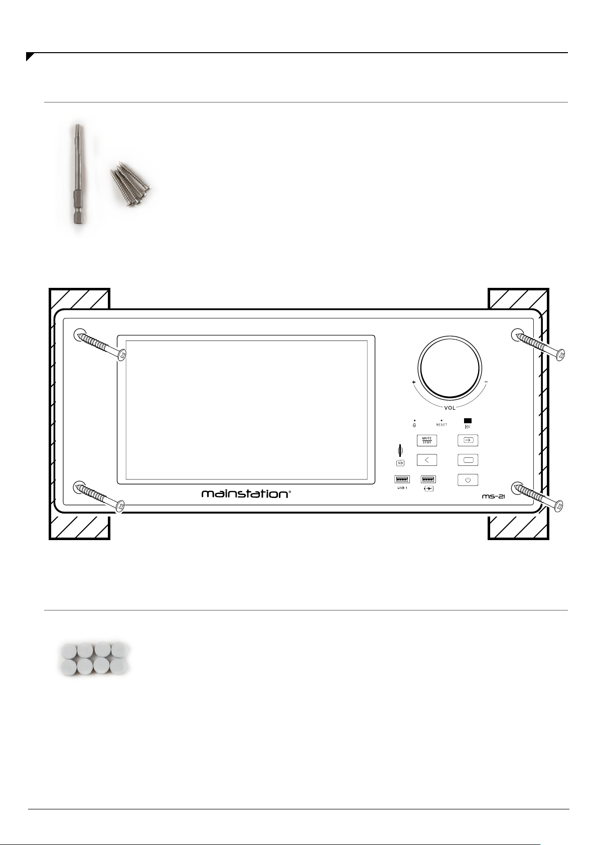
Press the supplied caps (x4) into the holes to cover the screws. Extra caps
are provided.
The caps can be removed by placing a sticky piece of tape or similar onto
the cap and pulling slowly outward. Alternatively, driving a sharp screw
into the cap and pulling outward is a method that works, but this damages
the screw cap.
After making all the necessary connections, use the 4 supplied Torx®screws
and supplied Torx driver to secure the unit to the wall. It is recommended that
you predrill the holes using a 3/32" (2.5mm) bit. Use care to keep the tip of the
driver from slipping out of the screw. Use of other screw types could lead to
damage of the MS-21 if the driver slips out.
INSTALLATION
Installing Screw Caps
Attaching to the Wall (continued)
Tabla de contenidos