Magna-Matic MAG-9000 Series Manual de usuario

Original Instructions
for Magna-Matic Lawn Mower
Blade Sharpeners
MAG-8000 SERIES [gen6]
MAG-9000 SERIES [gen7]
2
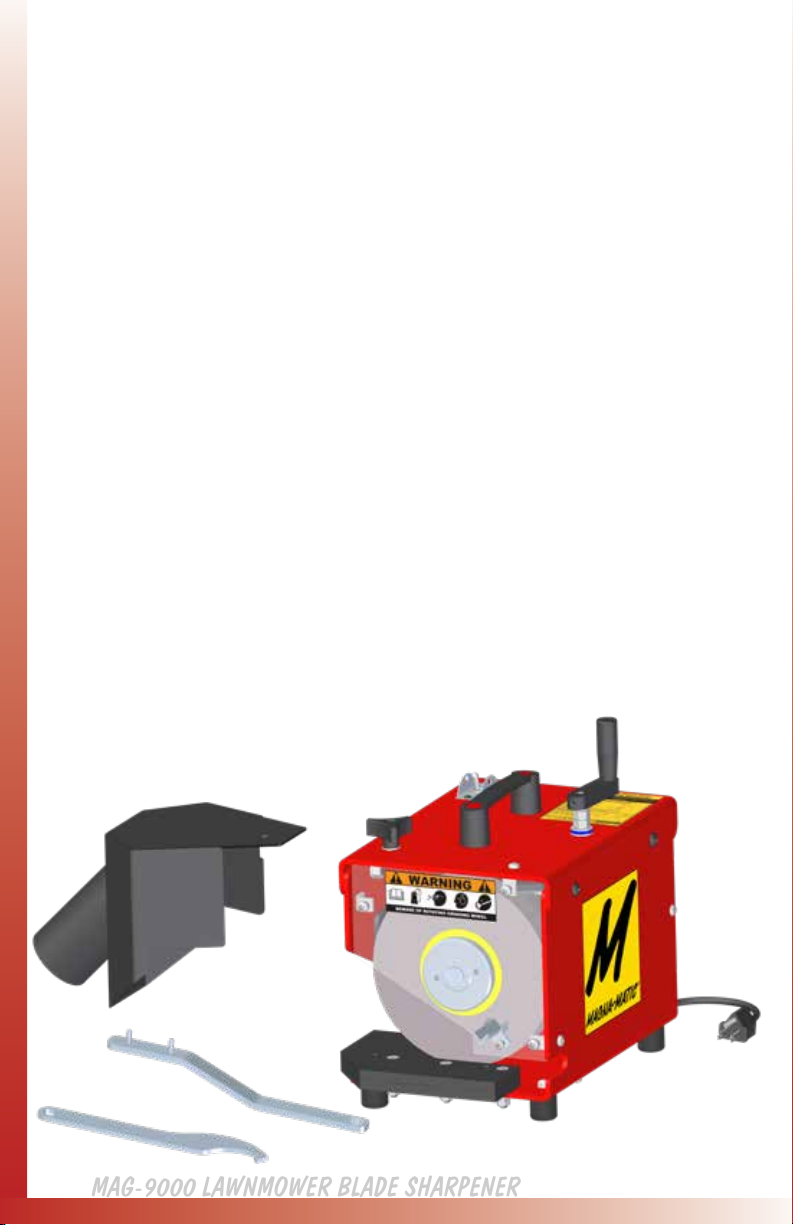
MAG-9000 LAWNMOWER BLADE SHARPENER
THANK YOU,
We sincerely appreciate your decision to make Magna-Matic your
lawn mower blade sharpener. We understand there are other choices in the
marketplace, and we are extremely condent that after the rst few blades
you sharpen, it will be evident you’ve chosen the best machine for the job.
Rest assured that if you have a question or problem you will have complete
customer support for all of our products.
800-328-1110 (USA & CANADA) or 920-564-2366
http://www.magna-matic.com
BOX INVENTORY
• MAG-9000 sharpener main body
• Vacuum grit guard (9000-50)
• Grinding wheel (9000-23) mounted
• Spanner wrench (9000-21)
• Arbor wrench (9000-53)
Please be sure all the items are in the box and inspect
for shipping damage, or for missing parts. Contact
Magna-Matic right away to remedy any problems due
to shipping. 800-328-1110

3
BOX INVENTORY
• MAG-8000 sharpener main body (with grit guard)
• Grinding wheel (9000-35)
• Grinding wheel (8000-30)
• Crank handle
• Flat worktable insert
• Rounded worktable insert (mounted on machine)
• Spanner wrench (9000-21)
• Arbor wrench (9000-53)
Please be sure all the items are in the box and inspect for
shipping damage, or for missing parts. Contact
Magna-Matic right away to remedy any problems due to
shipping. 800-328-1110
IMPORTANT - There is a transport bolt that must be
removed before use! The bolt goes through the two uprights and
the pivot plate. If this bolt is not removed it will be impossible to adjust
the grinding wheel. See page 6.

4
Before handling any equipment read
and understand the instructions.
THE SAFE WAY IS THE ONLY
WAY TO GRIND!
Grounding Instructions - This tool must be grounded while in use to protect the operator from electric shock. The tool is equipped
with an approved three conductor cord and three prong grounding type plug to t the proper grounding type receptacle. The green (or
green and yellow) wire is the grounding wire.
Extension Cords - Use only three wire extension cords which have three prong grounding type plugs and three pole receptacles which
accepts the tool’s plug. Replace or repair damaged cords.
Keep Work Area Clean - Clean benches and oors to prevent slip, trip, or falls.
Consider Working Environment - Don’t use power tools in damp or wet locations. Keep work area well lit. Don’t expose power tools to
rain. Do not use tool in presence of ammable liquids or gases.
Keep Children Away - All visitors should be kept a safe distance from the work area. Do not let visitors have contact with the tool or the
extension cord.
Store Idle Tools - When not in use, tools should be stored in dry, high or locked-up places out of reach of children.
Do Not Force Tool - It will do the job better and safer at the rate for which it was designed.
Do Not Over-Reach - Keep proper footing and balance at all times
Use Safety Glasses - Also face or dust mask-wrap around goggles, or other eye protection.
Wear Proper Apparel - Do not wear loose clothing or jewelry that can get caught in moving parts. Gloves and non-skid footwear are
required when working. Wear protective hair covering to contain long hair.
Do Not Abuse Cord - Never carry tool by cord or pull it to disconnect from receptacle.
Keep cord from heat, oil, and sharp edges.
Disconnect Tool - When not in use; before servicing; when changing grinding wheels.
Avoid Accidental Starting - Don’t carry plugged in tool. Be sure switch is o when plugging in.
Grinding Wheels - Use only grinding wheels having a maximum operating speed of 5500 RPM. KEEP GUARDS IN PLACE.
Guard Against Electrical Shock - Prevent body contact with grounded surface. For example: pipes, radiators, etc.
Stay Alert - Watch what you are doing. Use common sense. Do not operate tool when you are tired, or under the inuence of any
drugs or alcohol.
Check Damaged Parts - Before further use of the tool, a guard or other part that is damaged should be carefully checked to determine
that it will operate properly and perform its intended function. Check for alignment of moving parts, breakage of parts, mounting and
any other condition that eect its operation. All parts should be properly repaired or replaced. Do not use this tool if the switch does
not turn it on or o.
Never Leave Tool Unattended - Turn the power o. Don’t leave the tool until it comes to a complete stop.
Read “A Primer on Grinding Wheel Safety” http://www.magna-matic.com
WARNING
WHEN USING ELECTRIC TOOLS, BASIC
SAFETY PRECAUTIONS SHOULD ALWAYS
BE FOLLOWED TO REDUCE
THE RISK OF FIRE, ELECTRIC SHOCK,
AND PERSONAL INJURY.
CAUTION LAWN MOWER BLADES HAVE SHARP
EDGES - ALWAYS WEAR PROTECTIVE
GLOVES AND SAFETY GLASSES!

5
SAFETY LABELS
SAFETY COLOR DEFINITION
DANGER Interaction with the hazard will
cause severe injury or death.
WARNING Interaction with the hazard could
cause severe injury or death.
SAFETY
ICON DEFINITION
WARNING
Read all included
manuals and
bulletins included with
this equipment.
Always wear protective
gloves when operating
this equipment.
Gloves are required.
Always wear protective
eye wear when operating
this equipment.
Eye protection
required.
Always wear protective
hearing protection when
operating this equipment.
Hearing protection
required.
Always wear respiratory
protection when operating
this equipment.
Respiratory protection
required.
SAFETY
ICON DEFINITION
DANGER
Keep clear of the
grinding wheel.
Contact will cause
severe cuts or
abrasions.
Always keep safety
guards in place.
DANGER
Disconnect power
before servicing
machine
Always keep safety
panels in place.
WARNING
Keep clear of pulleys
and belts. Contact
will cause severe
injury.
Always keep safety
guards in place.

6
MAG-8000 LAWNMOWER BLADE SHARPENER
ASSEMBLY
IMPORTANT - There is a transport bolt that must be removed
before use! The bolt goes through the two uprights and the pivot plate. If this
bolt is not removed it will be impossible to adjust the grinding wheel. First
remove the grit guard, loosen the 5/16” bolt, and replace it with the plastic knob.
Then pull the grit guard outward and set it aside.
MOUNTING THE 1/2”
WIDE WHEEL, for
sharpening mulching
blades.
The 1/2” wide grinding
wheel requires the arbor
spacer.
The 1/2” wide wheel
will be in-line with the
rounded mulching blade
worktable insert. Be sure
the arbor spacer
(8000-27) is used as
shown in the image.
Use (2) 1/2” wrenches to remove the
transport bolt. Connect the crank handle
to the adjustment rod. Align the set
screw in the crank handle to the at on
the adjustment rod and tighten the set
screw (1/8” allen). You may need to
make a half-rotation on the crank handle
to loosen the pressure on the transport
bolt to remove it.

7
ASSEMBLY
TESTING THE MAG-8000
Before turning the unit on, test the unit by checking if the grinding wheel moves freely.
Ensure the MAG-8000 ON/OFF switch is in the OFF POSITION, plug the MAG-8000 into
a 20 amp, 110 volt outlet. Switch the ON/OFF switch to the ON POSITION to test the
motor. The motor should achieve FULL speed in 1-2 seconds. If it does not,
(see page 19) or contact MAGNA-MATIC (800-328-1110).
Steps to connect the grit guard to the MAG-8000.
1. The yellow ACTIVE GUARD must be on the inside of the black steel
guard by the motor.
2. The top lip of the grit guard must be on top of the yellow body plate of
the MAG-8000.
3. Slide the grit guard assembly into the MAG-8000 and the
interlocking tabs and lips will engage keeping the guards solid.
4. Screw the plastic knob into the threaded hole to hold the grit guard
assembly in place.
5. See top image on page 6, for a view on attaching the grit guard.
MOUNTING THE 1”
WIDE WHEEL, for
sharpening
straight-edged blades.
DO NOT USE the arbor
spacer when using the 1”
wide grinding wheel. Only
use the arbor nut.
WARNING
WHEN USING ELECTRIC TOOLS, BASIC
SAFETY PRECAUTIONS SHOULD ALWAYS
BE FOLLOWED TO REDUCE
THE RISK OF FIRE, ELECTRIC SHOCK,
AND PERSONAL INJURY.

8
MAG-8000 LAWNMOWER BLADE SHARPENER
ANGLE ADJUSTMENT
IMPORTANT - ALWAYS turn the MAG-8000 OFF when
changing or adjusting worktable inserts.
New [gen6] worktables (blade rest)
The new change to the MAG-8000 [gen6] is the implementation of worktable inserts. This new design
allows for future inserts for specic blades, and dierent size worktables. Additionally the worktable
insert provides the ability to dial in angles from 25º to 45º.
The worktable inserts slide into a fixed vice that is clamped by tightening a 5/16” bolt with the hex end
of the supplied spanner wrench or a 1/2” wrench.
The black flat worktable insert is for straight flat. (conventional blades)
The steel rounded worktable insert is for curved cutting edge. (mulching blades)
ABOVE: Worktable
position decal
RIGHT: Angle information
decal
Angle Indicators
These two decals are located on the
MAG-8000 they indicate worktable
positions required to achieve the listed
cutting edge angles.
30 degrees is the ONLY angle where the
worktable remains in one position over
the life of a grinding wheel. All other
angles require that the worktable be
moved to a position corresponding with
the chart on the MAG-8000. Use the
chart on the MAG-8000 (shown to the
right) to move the worktable insert when
the grinding wheel is at a diameter listed.
Note: the black
plastic wear plate is
reversible.
WARNING
WHEN USING ELECTRIC TOOLS, BASIC
SAFETY PRECAUTIONS SHOULD ALWAYS
BE FOLLOWED TO REDUCE
THE RISK OF FIRE, ELECTRIC SHOCK,
AND PERSONAL INJURY.

9
Worktable Set-up
The base of the worktable inserts are slotted.
Slide the worktable insert into the vice (shown below)
Once in place at the desired angle position, tighten the bolt in the worktable vice.
DO NOT OVER-TIGHTEN (only a 1/4 to 1/2 turn is required to clamp the insert.)
The spanner wrench has a 12 point hex wrench used for the bolt to tighten the insert in place.
A 1/2” wrench or socket can also be used.
Worktable Alignment
(Shown below) Align the front of the
insert to the line of the letter of the angle
position you desire. In the image the
insert is aligned to the letter B, which is a
45º @ 6” diameter grinding wheel. The
red arrow shows the front of the insert,
which is the part to align.
Left: View of the
spanner wrench used
to tighten the vice to
hold worktable inserts.

10
MAG-8000 LAWNMOWER BLADE SHARPENER
30 DEGREE ANGLE
MOST BASIC ANGLE - READ FOLLOWING INFO!
30 degrees is the most consistent and easiest angle to maintain in the
MAG-8000. It is also the industry average angle on most blades. If you are
looking for the most simple way to consistently sharpen your lawn mower blades,
use 30 degrees according to following instructions.
Align the worktable insert (at or rounded) to the 30º arrowed mark on the
worktable vice (see yellow decal in image below). This will make the insert
square to the vice (flush on back and front). Tighten it in place with the hex end of
the spanner wrench.
Lower the grinding wheel with the black crank handle on the top of the
MAG-8000, lower it as close as possible to the worktable without touching the
worktable (approx 1/32”), so you can just see a small space.
The worktable insert DOES NOT need to be moved to compensate for grinding
wheel diameter as other angles do. Simply keep lowering the grinding wheel
within a 1/32” from the worktable. See the red arrow, showing the approx. 1/32”
distance from the worktable to the wheel. Maintain this closeness to the
worktable to maintain the desired angle.
Este manual sirve para los siguientes modelos
1
Tabla de contenidos
Otros manuales de Herramientas eléctricas de Magna-Matic

Magna-Matic
Magna-Matic MAG-8200 Series Manual de usuario

Magna-Matic
Magna-Matic MAG-8100 Series Manual de usuario

Magna-Matic
Magna-Matic MAG-8100 Series Manual de usuario

Magna-Matic
Magna-Matic MAG-8000-7 Manual de usuario

Magna-Matic
Magna-Matic MAG-8000 Series Manual de usuario

Magna-Matic
Magna-Matic MAG-8200 Series Manual de usuario


