Lumel SM4 Manual de usuario

1
MODULE OF LOGIC OUTPUTS
SM4
USER’S MANUAL

2

3
1. APPLICATION................................................................................ 5
2. MODULE SET ................................................................................ 6
3. BASIC REQUIREMENTS AND OPERATIONAL SAFETY............ 6
4. INSTALLATION ............................................................................. 8
4.1. Module fitting .......................................................................... 8
4.2. Terminal description................................................................ 9
5. SERVICE ...................................................................................... 12
5.1. Description of the MODBUS protocol implementation ......... 13
5.2. Description of the MODBUS protocol functions ................... 14
5.3. Map of module registers....................................................... 17
5.4. Set of module registers ........................................................ 18
6. TECHNICAL DATA....................................................................... 23
7. BEFORE A DAMAGE WILL BE DECLARED.............................. 25
8. ORDERING CODES..................................................................... 26
9. MAINTENANCE AND GUARANTEE........................................... 27
Contents

4

5
Fig.1. View of SM4 module
1. APPLICATION
The SM4 module of logic outputs is destined to control simple actuators through
assignment of logic states received from the master device through the RS-485
interface.
The module can have 8 logic outputs or 4 relay outputs (depending on the execution)
and RS-485 and RS-232 interfaces with MODBUS RTU and ASCII transmission
protocols.
RS-232 and RS-485 ports are galvanically isolated from output signals and the
supply.
The module programming is possible by means of the RS-485 or RS-232 port.
A connecting wire to connect with the PC computer (RS-232) is included to the
SM4 module set.
Module parameters:
8 outputs of OC type or 4 relay outputs,
RS-485 communication interface with
MODBUS RTU and ASCII transmission
protocols to work in industrial systems with
an optical transmission signalling on LED
diodes,
Configurable baud rate: 2400....115200 bit/s

6
2. MODULE SET
The module set includes:
SM4 module ...................................................................................1 pc,
User’s manual ...............................................................................1 pc,
BU1005 plug with screw terminals .................................................2 pcs,
BU0204 plug with screw terminals .................................................2 pcs,
Hole plug of the RS-232 socket......................................................1 pc,
3. BASIC REQUIREMENTS AND OPERATIONAL SERVICE
Symbols located in this service manual mean:
WARNING!
Warning of potential, hazardous situations.
Especially important. One must acquaint with
this before connecting the module.
The non-observance of notices marked by these symbols can
occasion severe injuries of the personnel and the damage of
the instrument.
CAUTION!
Designates a general useful note. If you observe it, handling
of the module is made easier.
One must take note of this, when the instrument
is working inconsistently to the expectations.
Possible consequences if disregarded !
In the security scope the module meets the requirements of the EN 61010
-standard.
Remarks concerning the operator safety:
1. General
- The SM4 module is destined to be mounted on a 35 mm mounting rail.
- Non-authorized removal of the required housing, inappropriate use, incorrect instal-
lation or operation creates the risk of injury to personnel or damage to equipment.
For more detailed information please study the user’s manual.
- All operations concerning transport, installation, and commissioning as well as
maintenance must be carried out by qualified, skilled personnel and national
regulations for the prevention of accidents must be observed.
- According to this basic safety information, qualified, skilled personnel are persons
who are familiar with the installation, assembly, commissioning, and operation of

7
the product and who have qualifications necessary for their occupation.
2. Transport, storage
Please observe the notes on transport, storage and appropriate handling.
Observe the climatic conditions given in Technical Data.
3. Installation
- The meter must be installed according to the regulation and instructions given
in this user’s manual.
- Ensure proper handling and avoid mechanical stress.
- Do not bend any components and do not change any insulation distances.
- Do not touch any electronic components and contacts.
- Instruments may contain electrostatically sensitive components, which can easily
be damaged by inappropriate handling.
- Do not damage or destroy any electrical components since this might endanger
your health!
4. Electrical connection
- Before switching the instrument on, one must check the correctness of connection
to the network.
- In case of the protection terminal connection with a separate lead one must remem-
ber to connect it before the connection of the instrument to the mains.
- When working on live instruments, the applicable national regulations for the
prevention of accidents must be observed.
- The electrical installation must be carried out according to the appropriate regu-
lations (cable cross-sections, fuses, PE connection).
Additional information can be obtained from the user’s guide.
- The documentation contains information about installation in compliance withEMC
(shielding, grounding, filters and cables). These notes must be observed for all
CE-marked products.
- The manufacturer of the measuring system or installed devices is responsible for
the compliance with the required limit values demanded by the EMC legislation.
5. Operation
- Measuring systems including SM4 modules, must be equipped with protection
devices according to the corresponding standard and regulations for prevention
of accidents.
- After the instrument has been disconnected from the supply voltage, live compo-
nents and power connections must not be touched immediately because capacitors
can be charged.
- The housing must be closed during operation.
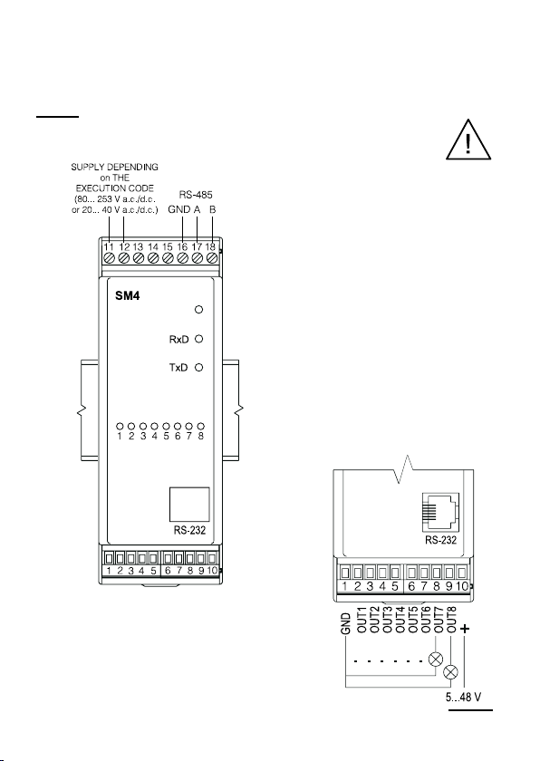
- The RS-232 socket serves only to connect the device (Fig. 5) working with the
MODBUS protocol.
When the module socket is not used place the hole plug.
6. Maintenance and servicing.
- Please observe the manufacturer’s documentation.

8
Fig.2. Overall and assembly dimensions
- Read all product-specific safety and application notes in this user’s manual.
Before taking the meter housing out, one must turn the supply off.
The removal of the instrument housing during the warranty contract period may
cause its cancellation.
4. INSTALLATION
4.1. Module fitting
The module is foreseen to be fixed on a 35 mm mounting rail (EN 60715)
The module housing is made of a non-flammable plastics.
Housing dimensions: 45 x 120 x 98 mm.
Connect external wires up to 2.5 mm2cross-section (from supply and interface side)
and up to 1.5 mm2(from output signals side).

9
Three diodes are located on the frontal
plate:
green - signals the supply
connection
green (RxD) - signals the data
reception by the
module
yellow (TxD) - signals the data
transmission by the
module
An example of logic output connection
of OC type is presented below
Fig.3. Electrical connections
of the SM4 binary output
module.
Fig. 4. Example of logic output
connection of OC type.
4.2. Terminal description
The supply and external signals must be connected in accordance with the description
from the fig. 3 and tables 1 and 2.
Notice:
One must pay particular attention to the correct connection of
external signals (see tables 1 and 2).

10
Description of SM4 logic output module
- Version with 8 outputs of OC type.
Terminal Terminal description
1 GND line of logic outputs
2 OUT1 line - output No 1
3 OUT2 line - output No 2
4 OUT3 line - output No 3
5 OUT4 line - output No 4
6 OUT5 line - output No 5
7 OUT6 line - output No 6
8 OUT7 line - output No 7
9 OUT8 line - output No 8
10 + line - output supply voltage
11, 12 Module supply lines
13...15 Not used
16 RS-485 interface mass with opto-isolation
17 Line Aof RS-485 interface with opto-isolation
18 Line Bof RS-485 interface with opto-isolation
Description of SM4 logic output module
- Version with 4 relay outputs.
Terminal Terminal description
1 GND line
2, 3 Output relay No 1
4, 5 Output relay No 2
6, 7 Output relay No 3
8, 9 Output relay No 4
10 5 V d.c. line
11, 12 Module supply lines
13...15 Not used
16 GND line of RS-485 interface with opto-isolation
17 Line Aof RS-485 interface with opto-isolation
18 Line Bof RS-485 interface with opto-isolation
Table 1
Table 2
Tabla de contenidos
Otros manuales de Unidad de control de Lumel
Manuales populares de Unidad de control de otras marcas

Festo
Festo Compact Performance CP-FB6-E Manual de lista de piezas

Elo TouchSystems
Elo TouchSystems DMS-SA19P-EXTME Manual de usuario

JS Automation
JS Automation MPC3034A Manual de usuario

JAUDT
JAUDT SW GII 6406 Series Guía rápida

Spektrum
Spektrum Air Module System Manual de usuario

BOC Edwards
BOC Edwards Q Series Manual de usuario


