LSG SPG-220 Manual de usuario
NOTE: This manual may be subject to updates or changes. Up to date manuals are available through our website at www.lsgfitness.com.au
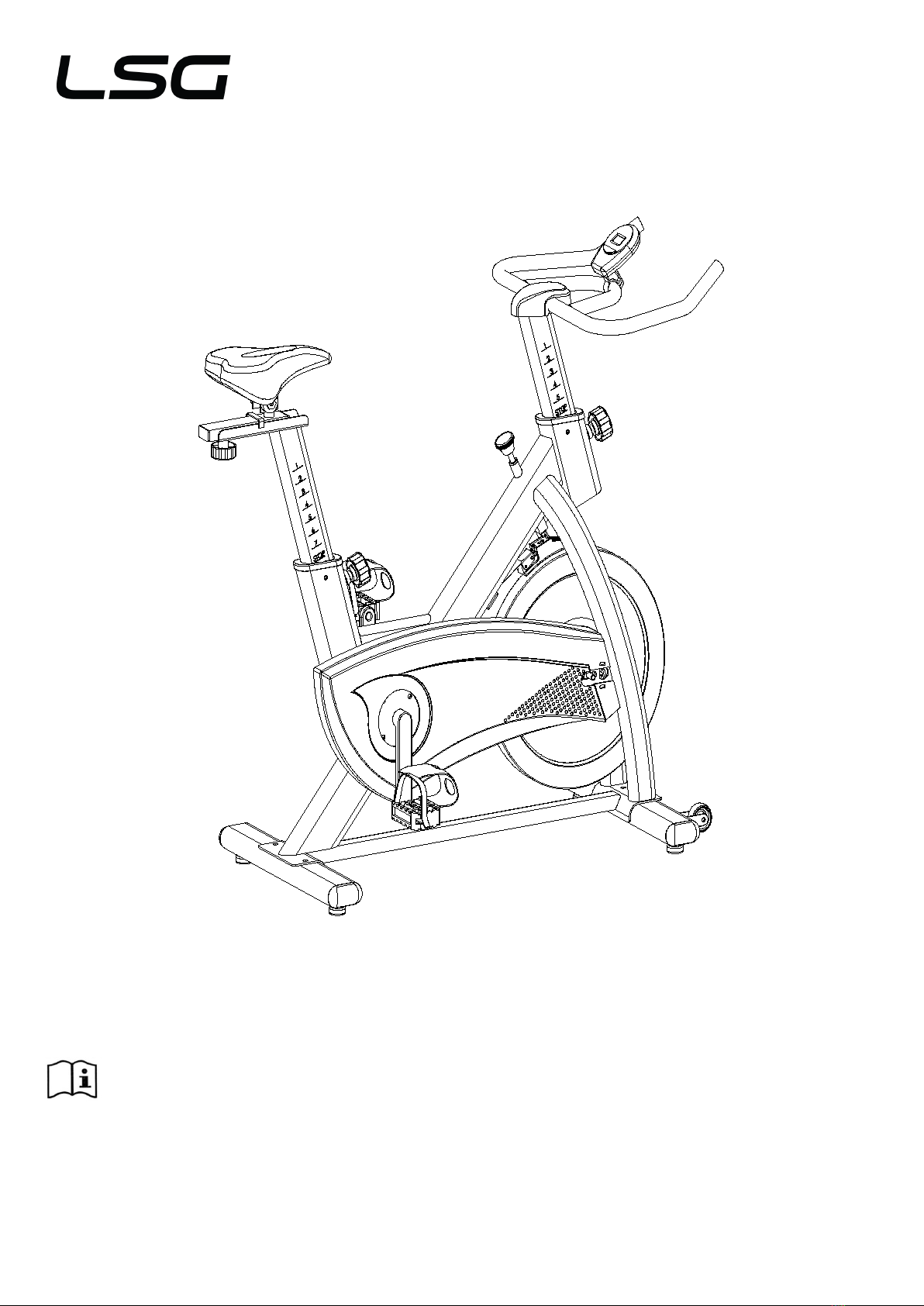
Product may vary slightly from the item pictured due to model upgrades
Read all instructions carefully before using this product. Retain this owner’s manual for future
reference.
SPG-220 SPIN BIKE
OWNER’S MANUAL

2
TABLE OF CONTENTS
1.IMPORTANT SAFETY INSTRUCTIONS 3
2. CARE INSTRUCTIONS 4
3. PARTS LIST 5
4. ASSEMBLY INSTRUCTION 7
5. ADJUSTMENT INSTRUCTIONS10
6. COMPUTER OPERATION 11
7. EXERCISE GUIDE 12
8. EXPLODED DIAGRAM 14
9. WARRANTY REGISTRATION 15

3
1. IMPORTANT SAFETY INSTRUCTIONS
WARNING - Read all instructions before using this machine.
It is important your machine receives regular maintenance to prolong its useful life. Failing to regularly
maintain your machine may void your warranty.
Please keep this manual with you at all times
a. It is important to read this entire manual before assembling and using the equipment. Safe and effective use
can only be achieved if the equipment is assembled, maintained and used properly.
Please note: It is your responsibility to ensure that all users of the equipment are informed of all warnings
and precautions.
b. Before starting any exercise program you should consult your doctor to determine if you have any medical
or physical conditions that could put your health and safety at risk, or prevent you from using the equipment
properly. Your doctor’s advice is essential if you are taking medication that affects your heart rate, blood
pressure or cholesterol level.
c. Be aware of your body’s signals. Incorrect or excessive exercise can damage your health. Stop exercising if
you experience any of the following symptoms: pain, tightness in your chest, irregular heartbeat, and
extreme shortness of breath, lightheadedness, dizziness or feelings of nausea. If you do experience any of
these symptoms, you should consult your doctor before continuing with your exercise program.
d. Keep children and pets away from the equipment. This equipment is designed for adult use only.
e. Use the equipment on a solid, flat level surface with a protective cover for your floor or carpet. To ensure
safety, the equipment should have at least 0.5 meters of free space all around it.
f. Before using the equipment, check that the nuts and bolts are securely tightened. If you hear any unusual
noises coming from the equipment during use and assemble, stop immediately. Do not use the equipment
until the problem has been rectified.
g. Wear suitable clothing while using the equipment. Avoid wearing loose clothing that may get caught in the
4
equipment or that may restrict or prevent movement.
h. This equipment is designed for indoor and family use only.
i. Care must be taken when lifting or moving the equipment so as not to injure your back.
j. Always keep this instruction manual and assembly tools at hand for quick reference.
k. The equipment is not suitable for therapeutic use.
l. There are many functions of the computer, which value will show when using the equipment according the
amount of exercise, here warmly remind you that the value of heart pulse just give you some reference.
2.CARE INSTRUCTIONS
a. Lubricate moving joints after periods of usage
b. Be careful not to damage plastic or metal parts of the machine with heavy or sharp objects
c. The machine can be kept clean by wiping it down using dry cloth
d. All nuts and bolts are to be checked and tightened on a regular basis. This includes pedals and other
moving parts. Failure to do so may cause damage to your thread and void your warranty.
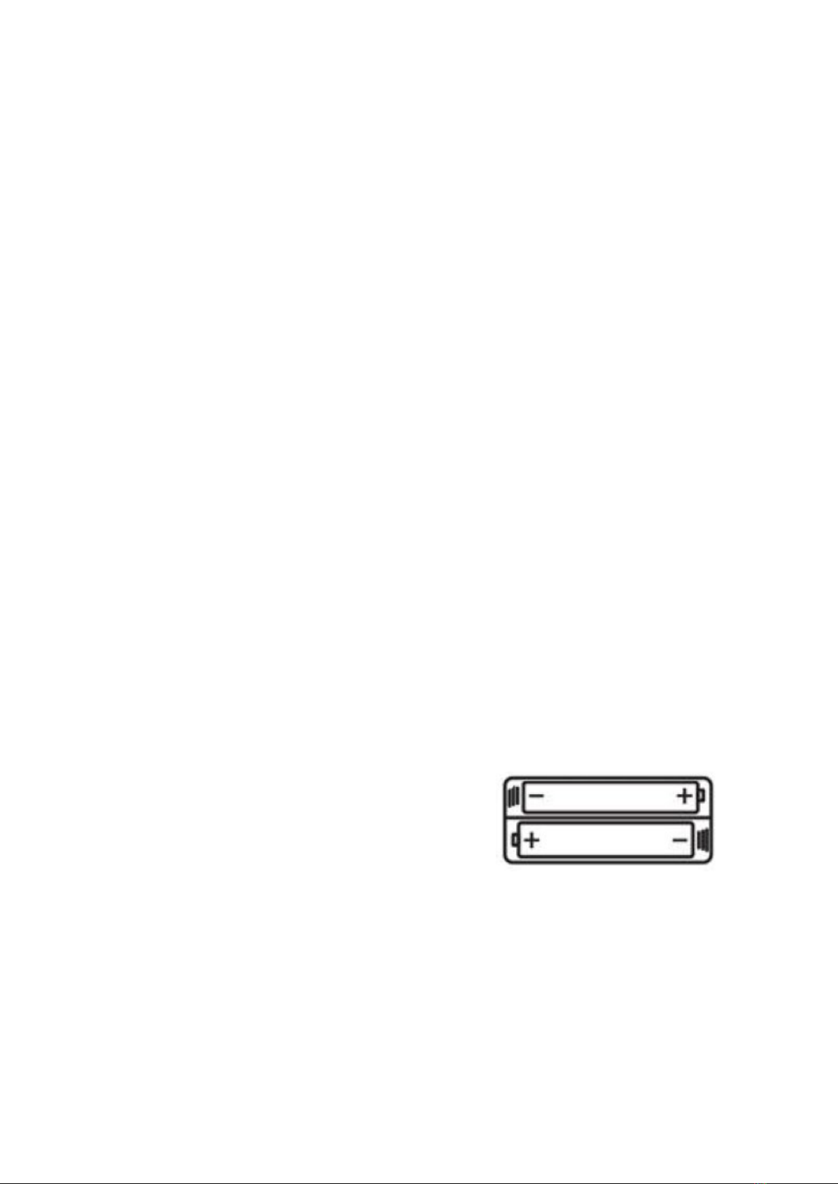
Battery Usage
a. Batteries are to be installed or replaced by adult only
b. Do not use rechargeable batteries. Do not mix different battery types. Do not mix old and new batteries.
Do not mix alkaline, standard (Carbon-Zinc), or rechargeable (Nickel-Cadmium) batteries
c. Remove batteries when product is not in use
d. Remove exhausted batteries from product and dispose of in accordance with the manufacturer’s
recommendation
e. Do not attempt to recharge non-rechargeable batteries
f. Batteries are to be inserted with correct polarity
g. The supply terminals are not to be short-circuited
5
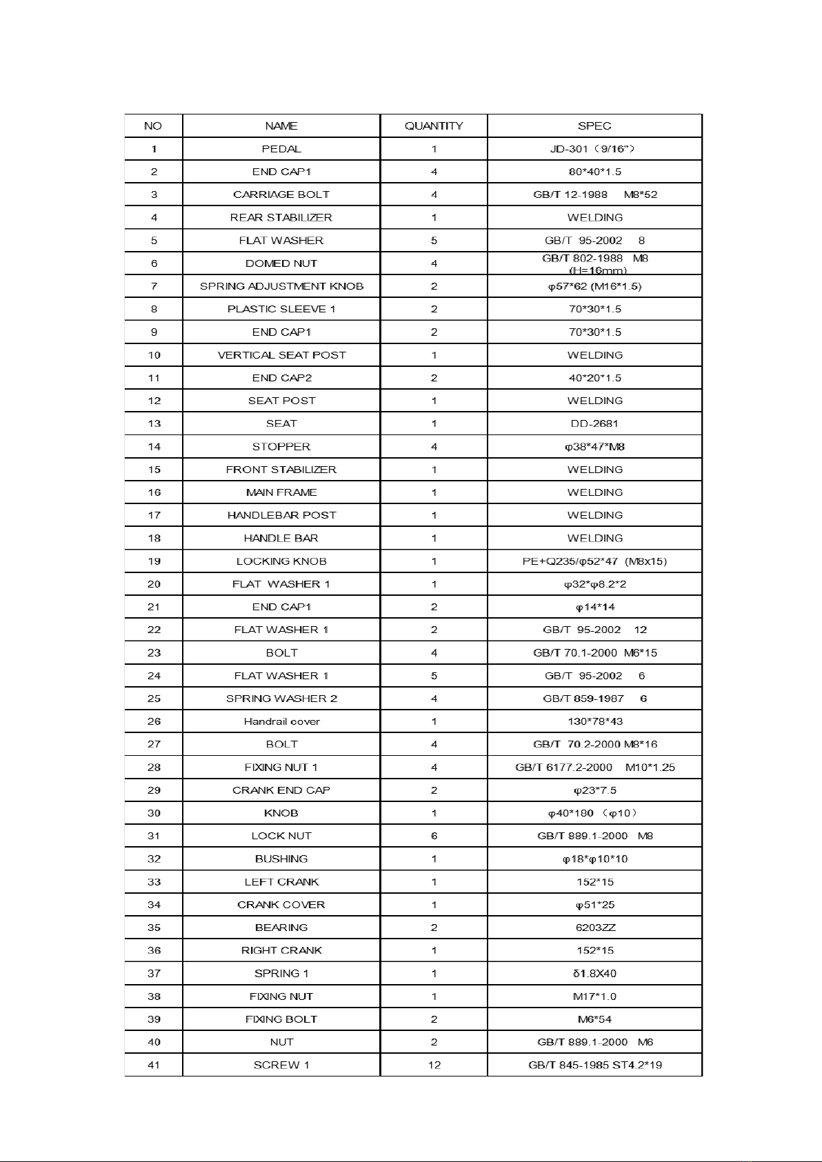
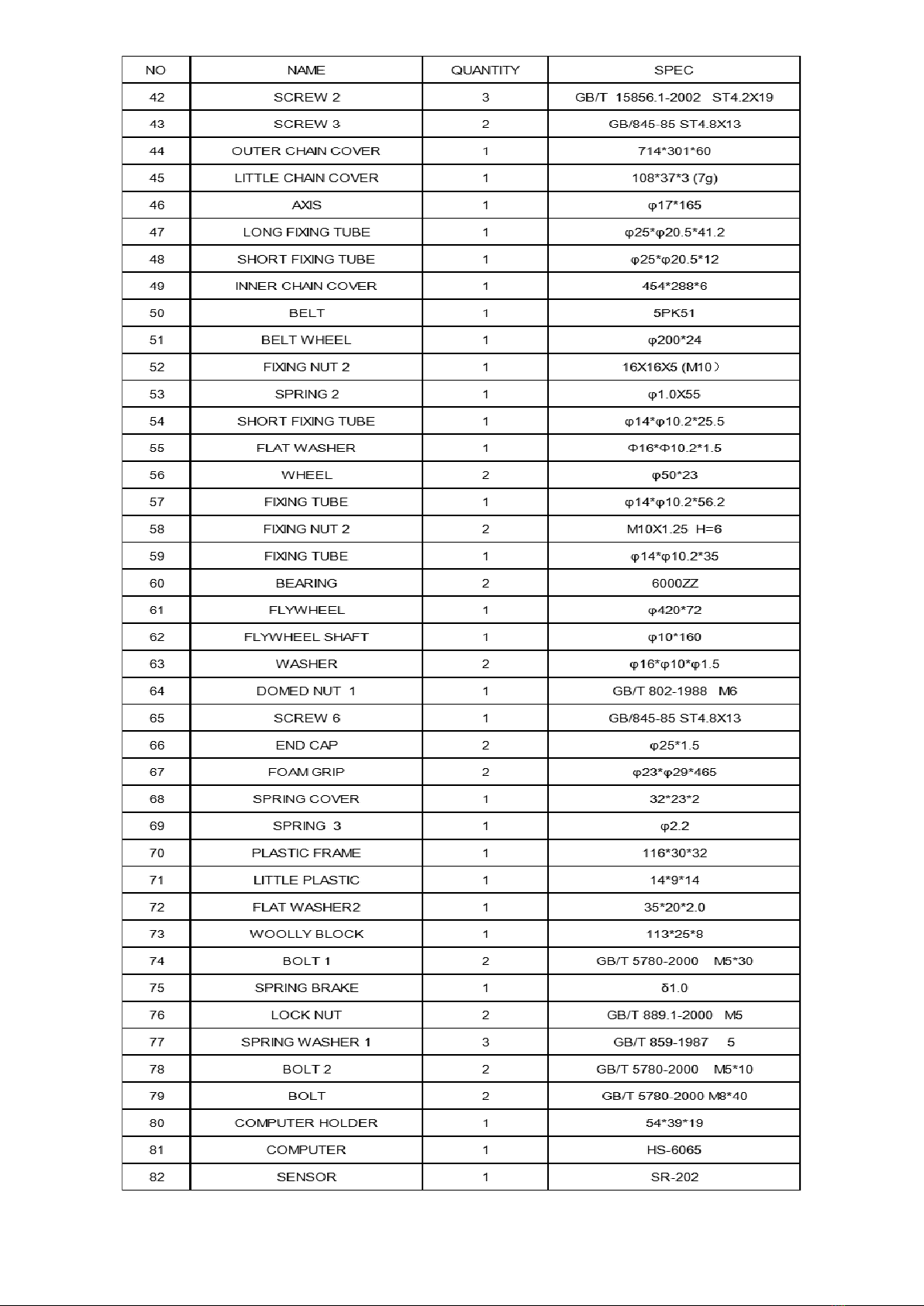
3.PARTS LIST
6
7
4. ASSEMBLY INSTRUCTIONS
A. Before assembling make sure that you will have enough space around the item.
B. Use the present tooling for assembling.
C. Before assembling please check whether all needed parts are available (at the above of this
instruction sheet you will find an explosion drawing with all single parts (marked with numbers)
which this item consists of.
STEP 1
STEP 2:
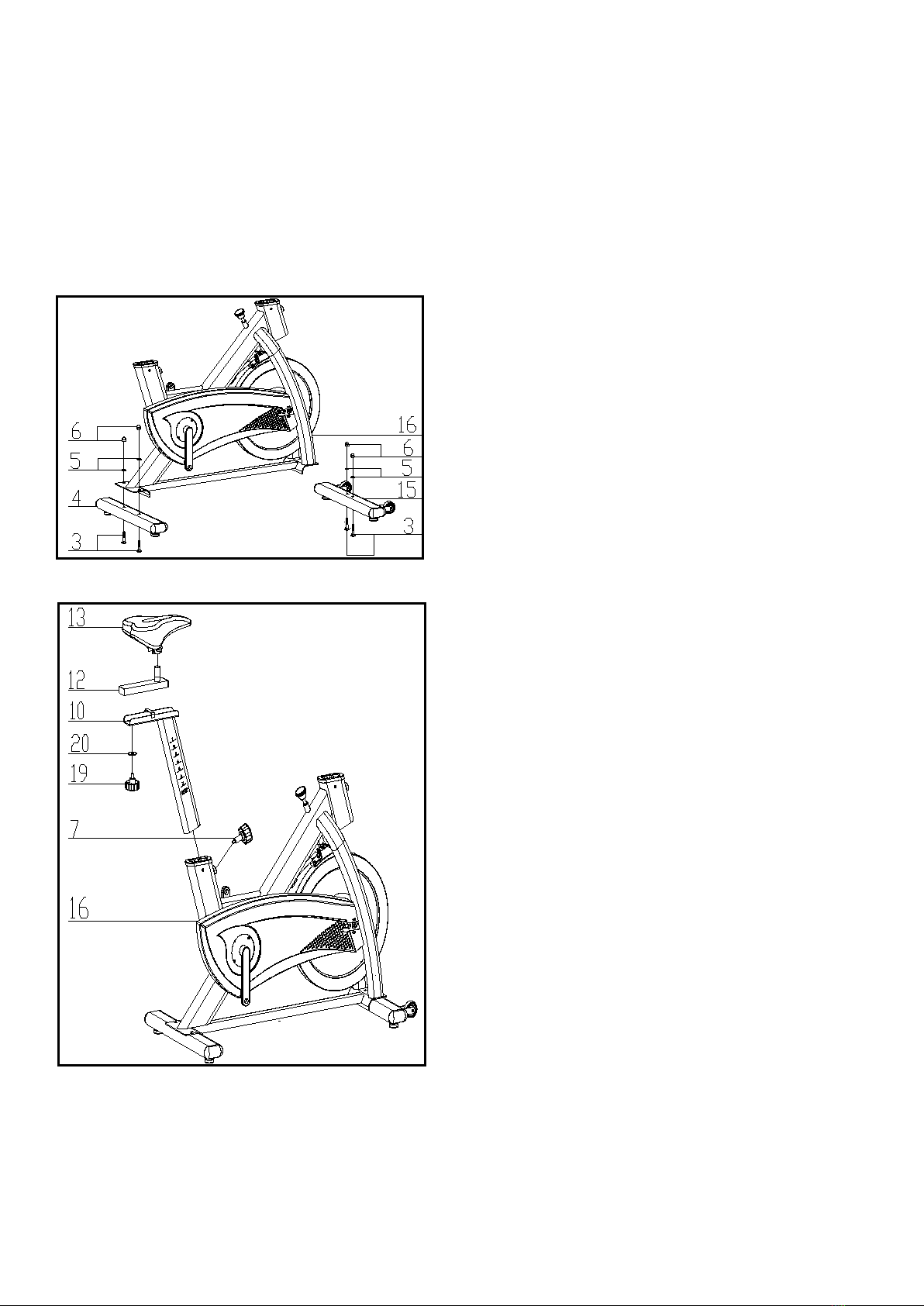
a) Attach the Front Stabilizer (pt.15) to the
Main Frame (pt.16) using two sets of Ø8
Flat Washers (pt.5), M8 Domed Nut (pt.6)
and M8*52 Carriage bolt (3).
b) Attach the Rear Stabilizer (pt.4) to the
Main Frame (pt.16) using two sets of Ø8
Flat Washers (pt.5), M8 Domed Nut (pt.6)
and M8*52 Carriage bolt (3).
a) First, the elastic bolt (7) of the large ball
head is loosened and pulled down, then
the cushion adjusting pipe assembly (10)
is inserted into the inner liner of the main
frame assembly (16) to make it in an
appropriate position, and then the elastic
bolt (7) of the large ball head is loosened
and locked.
b) At the same time, the buffer sliding tube
assembly (12) is inserted into the buffer
regulating tube assembly (10) and the
elastic bolt (7) of the large ball head is
locked by the buffer.
c) Finally, the buffer pad (13) is locked with a
tool (using a cross wrench).
8
STEP 3:
STEP 4:
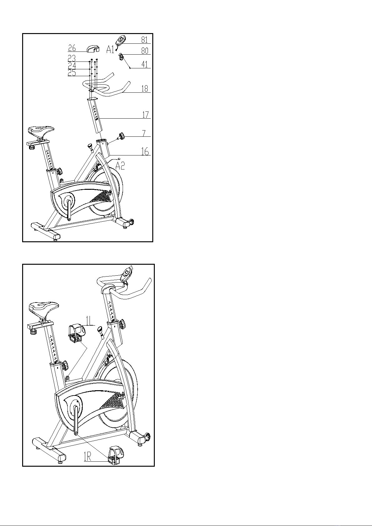
a) The Pedals (pt.1 L & pt.1 R) are marked
"L" and "R" - Left and Right. Connect
them to their appropriate crank arms. The
right crank arm is on the right- hand side
of the cycle as you sit on it.
Note that the Right pedal should be
threaded on clockwise and the Left pedal
anticlockwise.
a) First, the elastic bolt (7) of the large ball
head is relaxed and pulled down. Then,
the armrest regulating tube assembly (17)
is inserted into the inter-tube bushing of
the main frame assembly (16) to make it
in proper position. Then, the elastic bolt
(7) of the large ball head is released and
locked.
b) The armrest tube assembly (18) is then
fixed on the armrest regulating tube
assembly (17) with a light elastic washer
(24), a flat gasket (25) and an inner
hexagonal cylindrical screw (23), and the
armrest tube assembly (17) is locked.
Finally, the armrest cover (26) is clipped
to the armrest tube assembly (18).
ATTENTION: YOU SHOULD FIX THE
HANDLEBAR TIGHTLY
c) Fix the computer (81) onto the Handlebar
post (pt18) with 1pcs Bolt (41),connect A1
& A2.
9
STEP 5:
STEP 6:
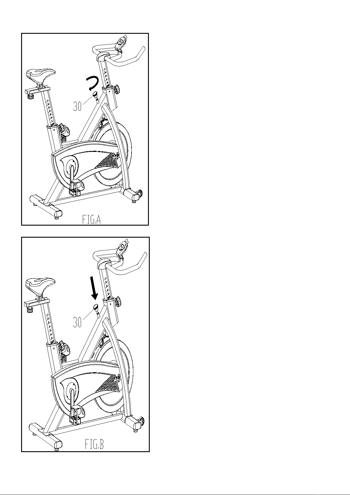
Using the Emergency Brake Function:
a) The same knob that allows you to adjust
the tension of the bike also doubles as the
Emergency
b) Brake. Use this safety feature in any
situation where you would need to get off
the bike and/or
c) stop the bike’s flywheel.
d) To use the Emergency Brake function in
any situation you would need it in, firmly
press down
e) on the Emergency Brake & Brake Control
Knob (#30).
Adjusting the Tension:
a) Increasing or decreasing the tension
allows you to add variety to your workout
sessions by adjusting
b) the resistance level of the bike.
c) To increase tension and increase
resistance (requiring more strength to
pedal), turn the Emergency
d) Brake & Tension Control Knob (#30) to
the right.
e) To decrease tension and increase
resistance (requiring less strength to
pedal), turn the Emergency
f) Brake & Tension Control Knob (#30) to
the left.

10
5. ADJUSTMENT INSTRUCTIONS
Vertical Seat Adjustment
To adjust the seat height, slacken the spring knob on the vertical post stem on the main frame and pull back
the knob. Position the vertical seat post for the desired height so that holes are aligned, then release the knob
and retighten it.
Horizontal Seat Adjustment
To move the seat forward in the direction of the handlebar or backwards away from it, loosen the adjusting
knob and washer and pull the knob back. Slide horizontal seat post into desired position. Align holes and then
retighten the adjusting knob.
Handlebar Height
To adjust the handlebar height, slacken the spring knob and secondary knob and pull both knobs back. Slide the
handlebar post along the housing on the main frame to the desired height and, with the holes aligned correctly,
tighten the spring adjusting knob and then the secondary knob.
Tabla de contenidos
Otros manuales de Bicicleta estática de LSG

LSG
LSG RB-100 Manual de usuario

LSG
LSG ERG-200 Manual de usuario

LSG
LSG EXER-10 Manual de usuario

LSG
LSG RB-1 Manual de usuario

LSG
LSG SPG-100 Manual de usuario

LSG
LSG RB-2 Manual de usuario

LSG
LSG ERG-400 Manual de usuario

LSG
LSG SPG-230 Manual de usuario

LSG
LSG SPG-210 Manual de usuario

LSG
LSG SPG-120 Manual de usuario


 Manual de usuario")


