LK MS-RE Series Manual de usuario

MS-RE Solar Inverter
User Manual
MS-RE 1 and MS-RE 2

2
MS-RE Solar Inverter
The MS-RE Solar Inverter range, is designed for locations having unreliable or limited access to electricity, to provide a reliable and aordable energy
access solution. It is designed to supply continuous energy from solar and grid based on availability.
The Inverter is customized to prioritize solar energy over grid supply. This helps to extract maximum energy from solar making it a sustainable energy
access solution for homes, micro enterprises, health centers, schools, and oces.
Do’s and Don’ts
MS-RE Solar Inverter
Battery
b Switch OFF and unplug the MS-RE Solar Inverter before touching
or cleaning the surface.
b Unplug the MS-RE Solar Inverter from the wall outlet during
lightning storm.
b Do not block the side ventilation slots by cloth or other material; it
may result in re hazard.
b Do not place the MS-RE Solar Inverter near heat radiation or heat
source.
b Do not install the MS-RE Solar Inverter near kitchen sink, laundry, wash
bowl and bathtub.
b Wear safety gloves and goggles.
b Use only battery grade water for battery relling.
b Install the battery in proper ventilated area.
b Apply petroleum jelly to terminals of the battery.
b Place battery horizontally and handle with care.
b Keep out of reach of children.
b Connect correct polarity of wires from MS-RE Solar Inverter to the
battery.
b Do not use impure or mineral water for battery relling.
b Do not add acid to the battery as it can damage the battery.
b Do not place the battery in the vicinity of water source or under direct
sunlight.
b Do not leave the battery's cell caps open.
b Do not increase the length of the battery wire.
b Do not place the battery at a height.
b Never short the terminals of the battery.
b Do not over ll the battery cells.
b Keep ammable substance away from the battery.
b Do not dispose the batteries in re.
b Do not open or mutilate the batteries.
b Do not keep tools or metal parts on the top surface of the battery.
For optimal Inverter usage, consider the following battery recommendations:

3
Description LED ON LED Blinking
1. ON/OFF SWITCH - -
2. MAINS ON Mains available -
3. SOLAR CHARGING Solar power available Charging through solar panel
4. MAINS CHARGING Battery charging through mains -
5. POWER SAVER Power saver is active -
6. BATTERY LOW Battery low trip Battery low pre-alarm
7. OVER LOAD Over load trip Over load alarm (slow blink), Short circuit (fast blink)
8. SYSTEM ON Inverter activated -
Front Panel Description: MS-RE 1
MS-RE Solar Inverter
1. ON-OFF SWITCH
Press and hold for 2 seconds for the device ON/OFF function.
2. MAINS ON
Indicates mains status.
3. SOLAR CHARGING
Indicates charging through solar panel.
4. MAINS CHARGING
Indicates charging through mains.
5. POWER SAVER
Indicates the power saver mode status.
6. BATTERY LOW
Indicates low battery status.
7. OVER LOAD
Indicates overload condition.
8. SYSTEM ON
Indicates inverter status.
9. QR CODE
Scan QR code for more product details
LED Indication
21
345 7
68
876
2 3 541
ON-OFF
SWITCH
SOLAR
CHARGING
MAINS
CHARGING
SYSTEM
ON
BATTERY
LOW
MAINS
ON
POWER
SAVER
QR CodeOVER
LOAD
9
9

4
Front Panel Description: MS-RE 2
1. ON-OFF SWITCH
Press and hold for 2 seconds for the device ON/OFF function and the backlight ON/OFF function.
2. LCD DISPLAY
Displays the various parameters on the LCD screen.
3. SAVE
Press to save the settings.
4. UP
Switch to change the value.
5. OK
Press to enter the selected setting.
6. QR Code
Scan QR code for more product details.
MS-RE Solar Inverter
2
3 54
1
ON-OFF
SWITCH
OKUP
LCD
DISPLAY
SAVE QR Code
6
21
3
4
56

5
To change the settings using LCD and switches:
1. Press OK and UP at the same time for 1 second to enter settings.
2. Use UP switch to navigate to the required setting.
3. Press OK to view the parameter setting options.
4. Use UP switch to scroll to the required option.
5. Press Save to conrm the option.
6. Press Save again to save the settings.
7. Press OK and UP at the same time for 1 second to exit settings.
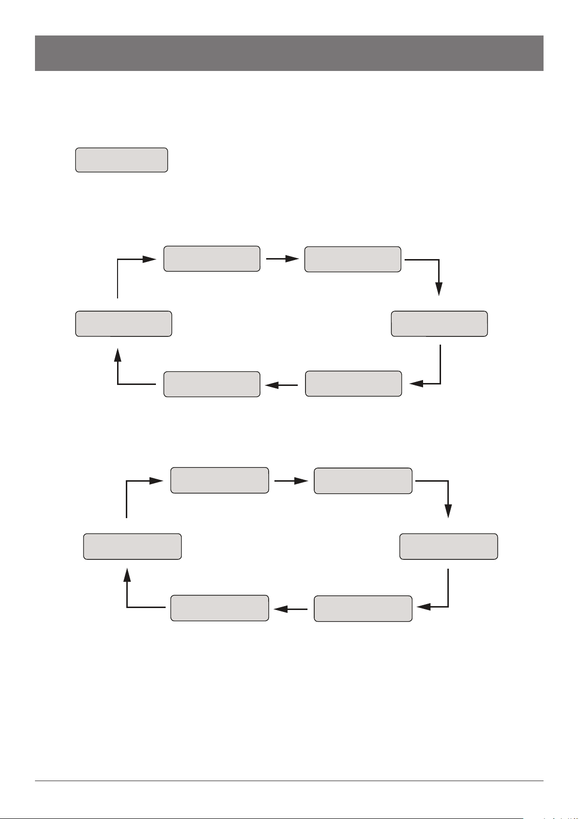
Conguration Settings: MS-RE 2
CONFIG SETTING
SAVED
CONFIG SETTING
MODE->Solar-Grid
CONFIG SETTING
MODE->Grid-Solar
CONFIG SETTING
CONFIG SETTING
SAVED
Press and hold for 1 second
CONFIG SETTING
MODE:: Solar-Grid
CONFIG SETTING
CONFIG SETTING
CONFIG SETTING
CONFIG SETTING
Select the preferred mode
CONFIG SETTING
NL SHUTDN:: XXX
CONFIG SETTING
CONFIG SETTING
CONFIG SETTING
SAVED
Select the preferred battery type
Select the preferred no load shutdown setting
BATT: :TUBULAR
MODE->Solar
BATT->TUBULAR
BATT->FLAT
BATT->GEL/VRLA
NL SHUTDN->DIS
NL SHUTDN->EN
MS-RE Solar Inverter
Battery
Grid input voltage
Ampere
Solar power
Cumulative solar energy
Selected charging mode
(Solar-Grid)
No load shutdown
AC output voltage
ON-OFF switch
Load percentage
Output AC frequency
Grid input fail
BATT:
I/P V:
A:
PV POWER:
CUM KWh:
SOL-GRID:
NL SHUTDN:
O/P V:
SW:
LD %:
FRQ:
FL:

6
HOMAYA SOLAR HYBRID SYSTEM
4
5
1
6
7
8
DC BATTERY INPUT - 12 V
CAUTION: ENSURE CORRECT TERMINALS OF BATTERY
MADE IN INDIA
MODEL NO.
S.NO.
AC INPUT
230V~50Hz
AC OUTPUT
FUS
PV
PANEL 12V
3
2
Back Panel Description: MS-RE 1
1. Mains Fuse
Connects to the input of the MS-RE Solar Inverter.
NOTE: In Mains mode, this fuse trips in case of short-circuit or overload at the output.
2. Universal Output Socket
Connects load through solar inverter.
3. Mains Input Cable (Input 230 V~ 50 Hz)
Connects input AC supply (the commercial supply) to the solar inverter.
4. Positive Battery Lead
Connects to the positive terminal of the battery.
5. Negative Battery Lead
Connects to the negative terminal of the battery.
6. Battery Type Selection Switch
Select the battery type (Tubular/Flat/Gel or VRLA) connected to the solar inverter.
7. Mode Selection Switch
Select the battery charging current prole (Solar/Solar+Grid/Grid+Solar). Refer to the technical specication section.
8. Terminal Block - PV Input
Connects to the PV panel input.
NOTE: Ensure the connections are as per the polarity markings and the screws tightened.
MS-RE Solar Inverter

7
5
1
3
6
4
2
DC BATTERY INPUT - 24 V
CAUTION: ENSURE CORRECT TERMINALS OF BATTERY
MADE IN INDIA
PV
PANEL 24V
AC OUTPUT
ON
AC MCB
AC INPUT
230V~50Hz
MODEL NO.
S.NO.
Back Panel Description: MS-RE 2
1. Mains input Cable (Input 230 V~ 50 Hz)
Connects input AC supply (the commercial supply) to the solar inverter.
2. AC Miniature Circuit Breaker
Connects to input of the Mains.
NOTE: In Mains mode, this breaker trips in case of short-circuit or overload at the output.
3. Universal Output Socket
Connects load through solar inverter.
4. Terminal Block - PV Input
Connects to the PV panel input.
NOTE: Ensure the connections are as per the polarity markings and the screws tightened.
5. Negative Battery Lead
Connects to the negative terminal of the battery.
6. Positive Battery Lead
Connects to the positive terminal of the battery.
MS-RE Solar Inverter
8
MS-RE Solar Inverter
Display Parameter: MS-RE 2
Power On Screen
UPS Mode Screen Loop
Mains Mode Screen Loop
Screen 1
Screen 2 Screen 3
Screen 4
Screen 5Screen 6
BATT V: XX.XX
I/P: XXX
SOLAR: XXX
A: XXX.X
PV POWER: XXXXW
CUM KWh: XXX.X
SYSTEM SETTING
SOL-GRID TUBULAR
NL SHUTDN: XX
POWER SAVER: XXX
O/P V: XXX SW XXX
LD%: XXX FRQ: XX.X
Screen 1
Screen 2 Screen 3
Screen 4
Screen 5Screen 6
BATT V: XX.XX
I/P: XXX
SOLAR: XXX
A: XXX.X
PV POWER: XXXXW
CUM KWh: XXX.X
SYSTEM SETTING
SOL-GRID TUBULAR
NL SHUTDN: XX
POWER SAVER: XXX
I/P V: XXX SW XXX
CHG: XXX FRQ: XX.X
S/W VERSION
V:X.X
Battery
Grid input voltage
Ampere
Solar power
Cumulative solar energy
Selected charging mode
(Solar-Grid)
No load shutdown
AC output voltage
ON-OFF switch
Load percentage
Output AC frequency
Grid input fail
BATT:
I/P V:
A:
PV POWER:
CUM KWh:
SOL-GRID:
NL SHUTDN:
O/P V:
SW:
LD %:
FRQ:
FL:

9
MS-RE Solar Inverter
Solar Generation History
Long press till you here a beep
Press to view the solar power generation
history of day 2–day 7
PV POWER: XXXXW
CUM KWh: XXX.X
Long press till the beep sound comes
to an exit
Press to exit solar power generation
PV POWER: XXXXW
CUM KWh: XXX.X
Press to select screen 4 from the loop
SOLAR HISTORY
DAY1: 0.00 Kwh
SOLAR HISTORY
DAY3: 0.00 Kwh
SOLAR HISTORY
DAY7: 0.00 Kwh
Screen 2
BATT V: XX.XX
I/P: XXX
Screen 3
SOLAR: XXX
A: XXX.X
Screen 4
PV POWER: XXXXW
CUM KWh: XXX.X
Screen 6
NL SHUTDN:XX
POWER SAVER:XXX
Screen 1
Screen 5
SYSTEM SETTING
SOL-GRID TUBULAR
Battery
Grid input voltage
Ampere
Solar power
Cumulative solar energy
Selected charging mode
(Solar-Grid)
No load shutdown
AC output voltage
ON-OFF switch
Load percentage
Output AC frequency
Grid input fail
BATT:
I/P V:
A:
PV POWER:
CUM KWh:
SOL-GRID:
NL SHUTDN:
O/P V:
SW:
LD %:
FRQ:
FL:

10
MS-RE Solar Inverter
Packaging Contents and Product Dimensions
MS-RE 1 Solar inverter
x1
Warranty card
Spare fuse (10 A)
x1
x1
x
1
MS-RE 2 Solar inverter
x1
Warranty card
x1
Battery Jointer Cable
x1
x
1
NOTE: Battery, solar panel and AC input socket are not included in the package.
Unpacking and Placement
On receiving the MS-RE Solar Inverter, unpack the inverter and check for physical damages that may have occurred to the inverter during transport.
Also, ensure the warranty card is available in the package.
After unpacking the MS-RE Solar Inverter, ensure:
Place the MS-RE Solar Inverter in an area that is protected from dust, water, heat, humidity, and away from ammable objects. Avoid inclined
planes for installation.
MS-RE 1 Solar Inverter
MS-RE 2 Solar Inverter
BATTERY
LOW
OVER
LOAD
POWER
SAVER
MAINS
CHARGING
SOLAR
CHARGING
MAINS
ON MS - RE 1
320 mm
302 mm
(313 mm)
12 mm
130 mm
(138 mm)
8 mm
OK UP SAVE MS - RE 2
320 mm
302 mm
(322 mm)
151 mm
(165 mm)
14 mm
21 mm
• The mains power input cable of the solar inverter is xed by a LTLK approved installer.
• The battery connector cables from the solar inverter is xed by a LTLK approved installer.
• The date of installation and seal of the installer is mentioned on the warranty card.
Este manual sirve para los siguientes modelos
2
Tabla de contenidos
Otros manuales de Inversor de LK


