Lindy 32655 Manual de usuario

© LINDY ELECTRONICS LIMITED & LINDY-ELEKTRONIK GMBH - FIRST EDITION (FEB 2010)
For Home and Office Use
Tested to Comply with
FCC Standards
IPower Control 4xDIN
User Manual English
LINDY No. 32655
www.LINDY.com

English Manual
English 2
Security Advise .....................................................................................................................3
Description............................................................................................................................3
Hardware ..............................................................................................................................4
Connections ......................................................................................................................4
Package Content...............................................................................................................5
Installation .........................................................................................................................5
Status LED ........................................................................................................................5
Configuration ........................................................................................................................6
DHCP ................................................................................................................................6
Network settings with GBL_Conf.......................................................................................6
Configuration via webinterface..............................................................................................7
Login .................................................................................................................................7
Configuration - Power Ports ..............................................................................................7
Configuration – IP Address ...............................................................................................8
Configuration - IP ACL ......................................................................................................8
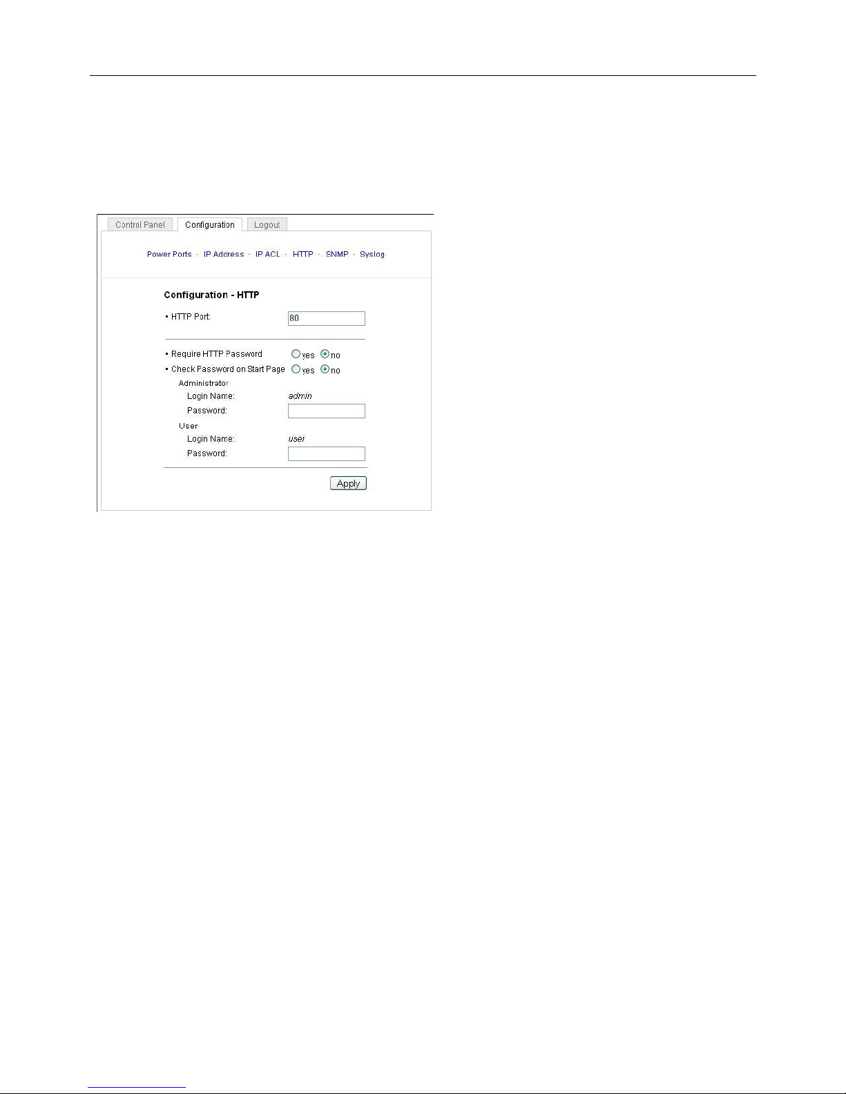
Configuration - HTTP ........................................................................................................9
HTTP Port .........................................................................................................................9
Configuration - SNMP ..................................................................................................... 10
Configuration - Syslog ..................................................................................................... 11
IP Access Control List......................................................................................................... 12
SNMP ................................................................................................................................. 12
SNMP-communities......................................................................................................... 12
SNMP-Traps ................................................................................................................... 12
Syslog ................................................................................................................................. 13
Operation ............................................................................................................................ 13
Switching by using the push buttons ..............................................................................13
Switching by Webinterface .............................................................................................. 13
Switching......................................................................................................................... 13
Batchmode.......................................................................................................................... 14
Switching via serial interface............................................................................................... 14
Features.............................................................................................................................. 15
Bootloader mode ............................................................................................................. 15
Firmware update ............................................................................................................. 15
Technical information ...................................................................................................... 15
Default settings................................................................................................................ 15

English Manual
English 3
Security Advise
The device must be installed only by qualified personnel according to the following installation
and operating instructions. The manufacturer does not accept responsibility in case of improper
use of the device and particularly any use of equipment that may cause personal injury or
material damage. The device contains no user-maintenable parts. All maintenance has to be
performed by factorytrained service personnel. Check if the power cord, the plug and the socket
are in proper condition. The device can be connected only to 230V AC (50 or 60 Hz) or 12/24V
DC power supply sockets. Always connect the device to properly grounded power sockets. The
device is intended for indoor use only. Do NOT install them in an area where excessive
moisture or heat is present. Because of safety and approval issues it is not allowed to modify
the device without our permission. Please note the safety advises and manuals of connected
devices, too. The device is NOT a toy. It has to be used or stored out or range of children.
Packaging material is NOT a toy. Plastics has to be stored out of range of children. Please
recycle the packaging materials. In case of further questions, about installation, operation or
usage of the device, which are not clear after reading the manual, please do not hesitate to ask
our support team.
Description
With LINDY IPower Control 4x DIN electrical devices can be switched via a TCP/IPwork.
There are only two steps necessary for installation: The connection to an electric circuit and a
TCP/IPwork and the configuration of the IP settings. Afterwards LINDY IPower Control 4x DIN
can be controlled by all PCs of thework.

English Manual
English 4
Hardware
Connections
1) Power Port LEDs
2) Power supply 24 V DC (Pins 1 and 2)
3) Button "select"
4) Button "ok"
5) status LED
6) Relais 1 (Pins 12 and 13)
7) Relais 2 (Pins 16 and 17)
8) Connector serial Interface (RS232)
9) Connector Ethernet (RJ45)
10)Relais 4 (Pins 34 and 35)
11)Relais 3 (Pins 30 and 31)
12)Emergency stop (Pins 24 and 25)
13)Power supply 230V AC (Pins 18 and 19)

English Manual
English 5
Package Content
Included in delivery are:
•LINDY IPower Control 4xDIN
•Short manual
Installation
1.) Connect the power supply cable to the power supply pins of
LINDY IPower Control and a socket. LINDY IPower Control
now is booting and shortly after ready for usage.
2.) Plug the Ethernet cable into the connector on the front side of
LINDY IPower Control 4x DIN and connect it to your
Ethernet.
3.) Connect the clients to the Power Ports of LINDY IPower Control.
Status LED
The Status LED shows different states of the device:
•Status LED red: Device is not connected to the ethernet
•Status LED orange: Device is connected to the ethernet, TCP/IP settings are not
allocated
•Status LED green: Device is connected to the ethernet, TCP/IP settings allocated, device
is ready to use
•Status LED blinks alternately red and green: Device is in Bootloader mode.

English Manual
English 6
Configuration
DHCP
After switch-on LINDY IPower Control looks for a DHCP server and requests an available IP
address (for deactivation of that feature see 2.2). Please check the IP adress allocated to
LINDY IPower Control in the DHCP server settings to make sure that the same address is
used at every reboot.
Network settings with GBL_Conf
For changing thework properties manually, the program GBL_Conf.exe is required. This tool is
available for free on our website www.lindy.com. Furthermore GBL_Conf.exe enables you to
install firmware updates and to reset LINDY IPower Control to its factory settings. Activate
bootloader mode of LINDY IPower Control and run GBL_Conf.exe. The program will look
automatically for connected devices and will display theirwork configuration.
If the displayed IP address accords with the factory settings (192.168.0.2), there is either no
DHCP server available in thework or no free IP address could be allocated. Enter a free IP
address and the accordingmask in the entry mask, then save these changes by clicking on
Program - Device - SaveConfig.
Restart the firmware of LINDY IPower Control, so that the changes will take effect. Now click
on Search in order to have thenewwork configuration displayed.

English Manual
English 7
Configuration via webinterface
Login
Go to the website of LINDY IPower Control.
Enter the IP address of LINDY IPower Control
into the address line of your internet browser:
http://”IP address of LINDY IPower Control”/
and press LOGIN. To enter the configuration
menu, click on „Configuration“ on the
upper left side of the screen.
Configuration - Power Ports
Label
A name with a maximum of 15 characters can be
entered here for each Power Port.
After power-up switch
The Power Port’s switching state after a power-on of
the device can be defined here (on, off, remember last
state).
If switching on after power-up, wait ...
A switching delay of a Power Port can be defined here that is applied after switch on of the
device. The delay can last up to 8191 seconds.
After turning off, wait ...
While this function is enabled, the Power Port will reactive after the stated time, when it got
switched off.

English Manual
English 8
Configuration – IP Address
All changes made here require a restart of the firmware to get valid.
Hostname
Enter the host name of LINDY IPower Control. LINDY
IPower Control uses this name to connect with a
DHCP server.
Special characters may result inwork malfunction.
IP Address
Here the IP address of LINDY IPower Control can be
changed.
Netmask
The subnet mask of the LINDY IPower Control may be changed here
.
Gateway
Here, the standard gateway of LINDY IPower Control can be set.
Use DHCP
Adjusts, whether LINDY IPower Control gets its TCP/ IP settings directly from your DHCP
server. If DHCP is activated, LINDY IPower Control proves, whether a DHCP server is active
within your LAN. Then LINDY IPower Control requests TCP/IP settings from this server. If
there is no DHCP server present inwork, we recommend to deactivate this option.
Configuration - IP ACL
Reply ICMP-Ping requests
Sets whether or not, the LINDY IPower Control shall
react on ping requests.
Enable IP Filter
The IP Access Control List (IP ACL) of LINDY IPower
Control can be activated here.
If IP ACL is active, DHCP and SNMP only work, if all
relevant servers and clients are registered in this list.
IPower Control 4

English Manual
English 9
Configuration - HTTP
All changes made here require a restart of the firmware to get valid.
HTTP Port
Enter the HTTP port number, if necessary.
Possible numbers are 1 ... 65534
(standard: 80). To get access to LINDY
IPower Control, you have to enter the port
number behind the IP address of LINDY
IPower Control, e.g.:
http://192.168.0.2:1720
Require HTTP Password
Password protected access can be
activated here. In this case, a user and an
administrator password have to be defined.
Passwords may have a maximum lengths
of 15 characters. Administrators are
authorized to switch all ports and to modify
the settings of LINDY IPower Control and
of all ports. The username of the administrator is “admin”.
Users are authorized to switch all ports but are not allowed to modify the settings of neither
LINDY IPower Control nor the ports. The username of the user is “user”. If you have forgotten
your password, activate the bootloader mode of LINDY IPower Control, start GBL-Conf.exe
and deactivate the password request.
Check Password on start page
If this option is activated, the user has to enter his password, before logging in to the web
interface.

English Manual
English 10
Configuration - SNMP
Please use these options only if yourwork is configured for SNMP!
Enable SNMP-get
SNMP-get protocol of LINDY IPower
Control can be activated here.
Community public
Determine the SNMP public
community here.
Enable SNMP-set
Activate SNMP-set protocol of LINDY
IPower Controlwith this option.
Community private
Determine the SNMP private
community here.
Download SNMP MIB
The MIBs of LINDY IPower Control may be downloaded here.
Este manual sirve para los siguientes modelos
1
Tabla de contenidos
Otros manuales de Unidad de control de Lindy
Manuales populares de Unidad de control de otras marcas

Festo
Festo Compact Performance CP-FB6-E Manual de lista de piezas

Elo TouchSystems
Elo TouchSystems DMS-SA19P-EXTME Manual de usuario

JS Automation
JS Automation MPC3034A Manual de usuario

JAUDT
JAUDT SW GII 6406 Series Guía rápida

Spektrum
Spektrum Air Module System Manual de usuario

BOC Edwards
BOC Edwards Q Series Manual de usuario


