Lincoln 3652 Manual de usuario

USER’S MANUAL
Have a technical question?
If you have questions, or require
technical service, please contact
our trained service technicians at:
1-314-679-4200 ext. 4782
Monday – Friday 7:30 am to 4:15 pm CST
Visit our web site at www.lincolnindustrial.com
for new products, catalogs, and instructions
for product use.
Need service parts?
To order replacement or service parts,
visit us online at www.lincolnindustrial.com
or call toll free 1-800-992-9898.
Owner/Operator Responsibility
It is the owner’s/operator’s responsibility to:
• Properly use and maintain this equipment.
• Read and understand the instructions and
warnings contained in this manual prior to
operating this equipment.
• Have the contents of this manual
explained in their native language if
they do not understand any of the
languages herein.
• Retain this manual for future reference
to important warnings, operating and
maintenance instructions.
Specifications:
Tank Capacity: 6 gallons (24 liters)
Max. Air Pressure: 150 PSI (10 bar)
Min. Air Pressure: 90 PSI (6 bar)
Max. Fluid Temperature: 176° F (80° C)
6-GALLON USED FLUID EVACUATOR
MODEL 3652
MARCH 2011 Form 403977 Section - B4-38

Page Number - 2 Form 403977
Table of Contents
Service Parts and Accessories . . . . . . . . . . . . .3
Introduction .............................4
Warnings and Precautions . . . . . . . . . . . . . . . . .4
Care and Maintenance . . . . . . . . . . . . . . . . . . . .4
Operation ..............................5
Emptying the Evacuator . . . . . . . . . . . . . . . . . . .6
Troubleshooting .........................6
Spanish ................................7
French ............................... 13
Warranty ............................. 19

Form 403977 Page Number - 3
9
31
32
3
4
7
10
11
8
29
30
28
27
26
25
24
23
12
13
14
1
20
2
5
17
19
18
16
15
22
21
6
13
33
34
35
36
Service Parts and Accessories
SERVICE/REPLACEMENT PARTS & KITS
Ref.
No. Part/Kit
No. Description Qty
1276741 Gauge Boot 1
2 Gauge 1
3
276744
Spring 1
4 Evacuation Hose 1
5 Rubber Grip 1
6 Ball Valve 1
7 Elbow 1
8 Wand Connector 1
9 O-ring 2
10 277540 Y Fitting 1
11
276740
Handle Grip 1
12 Handle 1
13 Cap Screw 2
14 276748 Cap 1
15 Gasket 1
16 276750 Chain 1
17 276749
(incl.
276750)
Cap Screw 1
18 Cap 1
19 Gasket 1
20 277227 Fitting 1
21 276745 Venturi Assembly (incl. 276759) 1
22 276759 Muffler 1
23 276747 Elbow 2
24 Sight Tube 1
25 276746 Wheel 1
26 Wheel Nut 1
27 276751 Mercedes Adapter 1
28 276752 BMW Adapter 1
29 276753 VW Adapter 1
30 276743 Wand Tube 1
31 Cap Screw 2
32 276754 Flexible Wand, 5mm, Red 1
33 276755 Flexible Wand, 6mm, Clear 1
34 276756 Flexible Wand, 8mm, Yellow 1
35 276757 Rigid Wand, 5mm 1
36 276758 Rigid Wand, 6mm 1
Page Number - 4 Form 403977
INTRODUCTION
Lincoln Model 3652 6-gallon Used Fluid Evacuator
is designed for evacuating fluids (except gasoline
or other fuels) from automotive reservoirs. Recom-
mended fluids include engine oil, gear and trans-
mission oils, power steering fluid, coolants, brake
fluid, and other similar fluids.
It utilizes a venturi that operates on compressed air
between 90 and 150 PSI (6 to 10 bar), to develop
vacuum in the 6-gallon (24-liter) tank. The vacuum
is transferred via an evacuation hose from the tank
to a wand or adapter, which is immersed into a res-
ervoir of fluid, and the fluid is drawn into the tank.
WARNINGS AND PRECAUTIONS
This equipment is designed for servicing a variety
of vehicles in a safe and convenient manner. How-
ever, due to the variation in vehicle design between
manufacturers, makes, models and years, oil
evacuation through the dipstick tube is not always
feasible or possible.
The procedures documented in this manual are to
serve as guidelines for general use of this equip-
ment. In addition to these guidelines, always follow
the vehicle manufacturer’s recommended proce-
dures when attempting to use this equipment.
Use common sense when operating this equip-
ment. If something does not seem or feel right,
stop immediately and consult a professional with
knowledge of the application. Don’t force the use
of this equipment on an application for which it is
not intended.
• Carefully read and understand these
instructions prior to using this equipment
• Always wear safety glasses when using this
equipment
• Avoid burns by remaining cautious of engine
parts that may become hot when the engine is
running
• Never operate this equipment on a vehicle with
the engine running
CARE AND MAINTENANCE
The evacuator does not require any particular
maintenance other than normal cleaning. The unit
should be cleaned using a cloth dampened with
water, alcohol, or detergent recommended for
household electrical appliances.
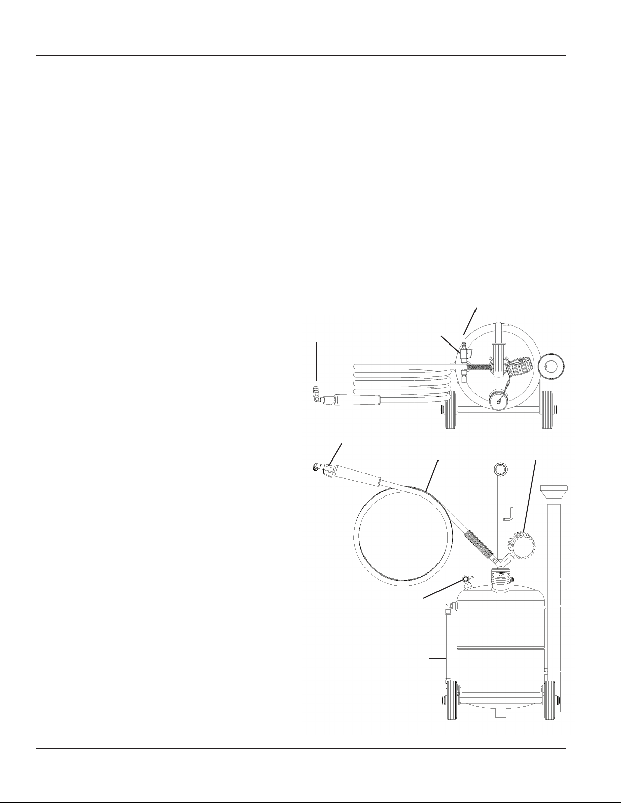
Compressed
Air Connection
(90 - 150 psi /
6 - 10 bar)
Connection
to Evacuation
Wand or Adapter Valve A
Valve B
Evacuation Hose Vacuum
Gauge
Venturi
Sight Level Tube

Form 403977 Page Number - 5
OPERATION
1. For best results, run the engine to warm up the oil. Oil tempera-
ture should be between 150° and 175° F (70° and 80° C) prior
to evacuation.
2. Place the vehicle transmission in park or neutral, apply the parking
brake, and turn off the key.
3. Open the hood and remove the dipstick.
WARNING: The motor must be off when performing oil evacua-
tion through the dipstick tube.
4. Select the evacuation adapter for the make and configuration of
the vehicle, or the appropriate evacuation wand with the largest
possible diameter to fit in the dipstick tube.
5. Install the evacuation adapter into the dipstick tube, or insert
the evacuation wand as deep as possible into the dipstick tube
without touching the bottom (Fig. 1).
WARNING: Do not force the evacuation wand into the crankcase.
Stop pushing the evacuation wand into the dipstick tube if resis-
tance is felt.
6. Close valve A between the venturi and the tank (Fig 2).
7. Close valve B near the suction end of the evacuation hose (Fig 3).
8. Connect a compressed air hose with pressure between 90 and
150 psi (6 – 10 bar) to the air nipple extending from the venturi
(Fig. 4).
9. Open valve A and allow the venturi to operate until the gauge
needle moves into the green zone (Fig. 5).
At this point the tank is fully charged. For the best performance,
leave the air hose connected to the venturi during evacuation to
maintain the vacuum charge in the tank. If the application is re-
mote from the compressed air supply, close valve A and discon-
nect the compressed air supply from the venturi. The tank will
maintain the initial charge until it has been used up during the
evacuation process.
10. Locate the evacuator so the evacuation hose is within reach of
the evacuation adapter or wand previously inserted in the dip-
stick tube.
11. Insert the suction end of the evacuation hose into the coupler
on the end of the evacuation adapter or wand (Fig. 6).
12. Open valve B on the end of the evacuation hose and allow the
evacuator to withdraw the desired amount of fluid (Fig. 7).
WARNING: Never fill the tank over the maximum limit shown on
the sight gauge located on the side of the tank.
13. Close valve B to stop evacuation (Fig. 8).
Fig. 1
Fig. 2
Fig. 3
Fig. 4
Fig. 5
Fig. 6

Page Number - 6 Form 403977
EMPTYING THE EVACUATOR
1. Release any vacuum remaining in the tank by opening valve B or
disconnecting the compressed air hose with valve A open.
2. With the compressed air hose disconnected, close valve A.
3. Unscrew the drain cap and tilt the tank up to pour the fluid into
an appropriate storage container.
WARNING: To prevent fluid from entering the venturi, always
ensure valve A is closed before tilting the unit to drain.
TROUBLESHOOTING
No vacuum is being developed
1. Check the air pressure to the venturi. It must
be at least 90 PSI (6 bar).
2. Ensure the valve at the end of the evacuation hose is closed.
3. Ensure the valve between the venturi and the tank is open.
4. Damaged gauge – replace if necessary.
5. Ensure the muffler at the outlet of the venturi
is not clogged or restricted.
Vacuum gauge is not functioning
1. Replace the vacuum gauge if it has been bumped or damaged
2. Remove the gauge and check that the inlet is not blocked
Fluid will not evacuate
1. Ensure the valve at the end of the evacuation hose is open.
2. If evacuating oil, warm it up to at least
150° F (70° C).
3. Evacuation wand may be against bottom of reservoir. Lift the
wand out a little.
4. Check the evacuation wand for obstruction.
Unit will not maintain vacuum
1. Check the evacuation hose and fittings
for leaks.
2. Check the o-rings in the evacuation hose to wand connection.
Replace if worn.
3. Ensure the caps are tight.
4. Check the valve between the venturi and tank to ensure it is
closed and functioning properly.
Fig. 7
Fig. 8

MANUAL DEL USUARIO
¿Tiene alguna duda técnica?
Si tiene dudas, o requiere servicio técnico,
póngase en contacto con nuestros técnicos
de servicio capacitados llamando al:
1-314-679-4200 ext. 4782
Lunes a viernes de 7:30 am a 4:15 pm,
hora central estándar
Visite nuestro sitio web en www.lincolnindustrial.com
para obtener información sobre nuevos productos,
catálogos e instrucciones pare el uso del producto.
¿Necesita piezas de reparación?
Para pedir piezas de repuesto, visítenos
en línea en www.lincolnindustrial.com o
llame gratuitamente al 1-800-992-9898.
Responsabilidad del propietario / operador
El propietario / operador es responsable de
lo siguiente:
• Usar y efectuar el mantenimiento de este
equipo de forma apropiada.
• Leer y entender las instrucciones y
advertencias contenidas en este
manual antes de hacer funcionar
este equipo.
• Explicar el contenido de este manual
en su idioma nativo si no se entiende
ninguno de los idiomas en que está escrito.
• Conserve este manual como referencia en
el futuro a advertencias importantes e
instrucciones de operación y mantenimiento.
Especificaciones:
Capacidad del tanque: 6 galones (24 litros)
Presión máx. del aire: 150 PSI (10 bares) Presión
mín. del aire: 90 PSI (6 bares)
Temperatura máx. del fluido: 176 °F (80 °C)
EVACUADOR DE FLUIDO
USADO DE 6 GALONES
MODELO 3652
MARZO 2011 Formulario 403977 Sección - B4-38

Número de página - 8 Formulario 403977
Índice
Piezas y accesorios de servicio . . . . . . . . . . . .9
Introducción .......................... 10
Advertencias y precauciones. . . . . . . . . . . . . 10
Cuidado y mantenimiento . . . . . . . . . . . . . . . 10
Operación ............................ 11
Vaciado del evacuador . . . . . . . . . . . . . . . . . . 12
Resolución de problemas . . . . . . . . . . . . . . . 12
Garantía ............................. 20

Formulario 403977 Número de página - 9
Piezas y accesorios de servicio
PIEZAS DE SERVICIO/REPUESTO Y JUEGOS
N° de
ref.
N° de
pieza /
juego Descripción Cant.
1276741 Funda del manómetro 1
2 Manómetro 1
3
276744
Resorte 1
4 Manguera de evacuación 1
5 Empuñadura de caucho 1
6 Válvula de bola 1
7 Codo 1
8 Conector de la varilla 1
9 Junta tórica 2
10 Conexión en "Y" 1
11
276740
Empuñadura de mango 1
12 Mango 1
13 Tornillo 2
14 276748 Tapa 1
15 Empaquetadura 1
16 276750 Cadena 1
17 276749
(incl.
276750)
Tornillo 1
18 Tapa 1
19 Empaquetadura 1
20 277227 Conexión 1
21 276745 Conjunto de venturi
(incl. 276759) 1
22 276759 Silenciador 1
23 276747 Codo 2
24 Mirilla 1
25 276746 Rueda 1
26 Tuerca de rueda 1
27 276751 Adaptador de Mercedes 1
28 276752 Adaptador de BMW 1
29 276753 Adaptador de VW 1
30 276743 Tubo de la varilla 1
31 Tornillo 2
32 276754 Varilla flexible roja de 5
mm 1
33 276755 Varilla flexible
transparente de 6 mm 1
34 276756 Varilla flexible amarilla
de 8 mm 1
35 276757 Varilla rígida de 5 mm 1
36 276758 Varilla rígida de 6 mm 1
9
31
32
3
4
7
10
11
8
29
30
28
27
26
25
24
23
12
13
14
1
20
2
5
17
19
18
16
15
22
21
6
13
33
34
35
36

Número de página - 10 Formulario 403977
INTRODUCCIÓN
El evacuador de fluido usado de 6 galones de Lincoln
Modelo 3652 está diseñado para evacuar fluidos (ex-
cepto gasolina u otros combustibles) de los depósitos
automotrices. Entre los fluidos recomendados se incluy-
en el aceite de motor, aceite de engranajes y transmis-
ión, fluido de servodirección, refrigerantes, fluido para
frenos y otros fluidos similares.
Utiliza un venturi que funciona con aire comprimido a
una presión de 90 a 150 PSI (6 a 10 bares) para producir
un vacío en el depósito de 6 galones (24 litros). El vacío
se transfiere por medio de una manguera de evacuación
desde el tanque hasta una varilla o un adaptador, que
está sumergido en un depósito de fluido, y el fluido es
atraído hacia el tanque.
ADVERTENCIAS Y PRECAUCIONES
Este equipo está diseñado para efectuar el servicio de
una variedad de vehículos de una manera segura y con-
veniente. No obstante, debido a la variación de diseño
del vehículo entre fabricantes, marcas, modelos y años,
no siempre es posible o viable evacuar el aceite por el
tubo de la varilla indicadora
Los procedimientos documentados en este manual
deben servir como guías para el uso general de este
equipo. Además de estas guías, siga siempre los pro-
cedimientos recomendados por el fabricante al tratar de
usar este equipo.
Haga uso de su sentido común al hacer funcionar este
equipo. Si hay algo que no parece que esté bien, detén-
gase inmediatamente y consulte con un profesional que
tenga conocimientos de la aplicación. No fuerce el uso
de este equipo en una aplicación para la que no está
diseñado.
• Lea detenidamente y entienda las instrucciones antes
de usar este equipo.
• Lleve siempre gafas de seguridad al usar este equipo
• Evite quemaduras teniendo cuidado de las piezas del
motor que puedan calentarse cuando el motor está
en marcha
• No haga funcionar este equipo en un vehículo con el
motor en marcha
CUIDADO Y MANTENIMIENTO
El evacuador no requiere ningún mantenimiento par-
ticular además de la limpieza normal. La unidad debe
limpiarse usando un paño humedecido en agua, alcohol
o detergente recomendado para aparatos eléctricos
caseros.
Conexión de aire
comprimido
(6 a 10 bares /
90 a 150 lb/pulg²)
Conexión a la varilla
de evacuación o al
adaptador Válvula
A
Válvula B
Manguera de evacuación Manómetro
de vacío
Venturi
Tubo de mirilla
de nivel
Tabla de contenidos
Idiomas:


