Lilin PS3268C Manual de usuario

i
PS3268C
24-Port Web Smart GbE PoE+ Switch
QUICK INSTALLATION GUIDE

ii
Contents
Chapter 1 Introduction........................................................................1
Overview ........................................................................................................................................1
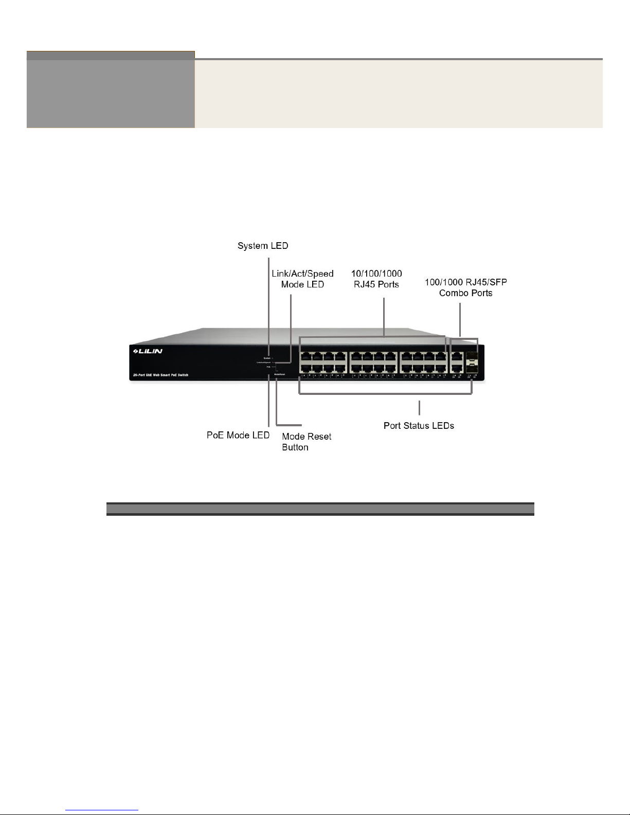
Front panel of the Switch.........................................................................................................1
Rear panel of the Switch .........................................................................................................2
Chapter 2 Installing The Switch.........................................................3
Package Contents......................................................................................................................4
Mounting the Switch in a 19-inch Rack..............................................................................4
Mounting the Switch on Desk or Shelf ...............................................................................5
Connecting the AC Power Cord............................................................................................6
Installing SFP Modules.............................................................................................................7
Connecting Console Port ........................................................................................................7
Chapter 3 Managing Switch Using the Web Interface ....................8
Manage the Switch Using Web Browser ...........................................................................8
Chapter 4 Troubleshooting ................................................................9
Appendix A Technical Specifications .................................................10
Hardware Specification ......................................................................................................... 10
1000 MBPS Gigabit Ethernet Collision Domain .......................................................... 11

1
Chapter 1 Introduction
Overview
PS3268C is a 26 ports GbE PoE web smart+ Switch. PS3268C provide high-performance, IEEE-
compliant network solutions. They include powerful management features that you can use to boost
performance, and increase productivity.
This guide describes hardware installation and basic troubleshooting for these managed switches.
Front panel of the Switch
Figure 1 Front panel of the switch
Table 1 Port Status LEDs
LED
Condition
Status
TP (Link/Act/Speed)
Green/Blink
Lit Green when TP link on 1000Mbps
Amber when TP link on 10/100Mbps
TP (PoE)
Green/Off
Lit Green when PoE link good
SFP (Link/Act/Speed)
Green/Blink
Lit Green when SFP link good
Lit Green when SFP link on 1000Mbps.
Amber when SFP link on 100Mbps

2
Table 2 System Status LED
SYSTEM LED
Condition
status
System
Green
OFF
Lit when power is coming up
Table 3 Mode Status LED
LED
Condition
Status
Link/ACT/Speed
Green
Yellow
OFF
Green when the link on 1000Mbps
Yellow when the link on 100Mbps
Off when the link on 10Mbps
PoE
Green
OFF
Lit Green shows all LED of each port are in PoE
Mode
Rear panel of the Switch
Figure 2 Rear panel of the switch
AC Power Socket

3
Chapter 2 Installing The Switch
C
AUTION
:
Circuit devices are sensitive to static electricity, which can
damage their delicate electronics. Dry weather conditions or walking
across a carpeted floor may cause you to acquire a static electrical
charge.
To protect your device, always:
•Touch the metal chassis of your computer to ground the static
electrical charge before you pick up the circuit device.
•Pick up the device by hold it on the left and right edges only.
•If you use outdoor device connected to switch with cable then you
need to install a surge arrester in between outdoor device and switch.
Figure 3 Add a surge arrester between outdoor device and switch
NOTE:The switch is an indoor device; if it is to be used with outdoor
devices such as outdoor IP camera or outdoor WiFi AP, then users
must install a surge arrester to protect the switch
W
ARNING
:
•Self-demolition on Product is strictly prohibited. Damage caused by
self-demolition will be charged for repairing fees.
•Do not place the switch in outdoor environment.
•Before installation, please make sure the input power source meeting
the product specification
•Before importing / exporting configuration file, please make sure the
firmware version is always the same.

4
Package Contents
PS3268C GbE Management Switch
Four adhesive rubber feet
Mounting Accessory (for 19” Rack Shelf, Optional)
Installation Guide
AC Power cord
Console cable
Mounting the Switch in a 19-inch Rack
Step1. Attach the mounting brackets to both sides of the chassis with screws.
Figure 4 Attaching mounting brackets to the switch
Step2. Place the switch on a rack shelf in the rack. Push the switch in until the oval holes in the
brackets align with the mounting holes in the rack posts.
Step3. Attach the mounting brackets to the rack posts with screws.
Figure 5 Attaching mounting brackets to the rack post

5
Mounting the Switch on Desk or Shelf
Step1. Verify that the workbench is sturdy and reliably grounded.
Step2. The rubber feet are included in the accessory kit. Attach the four adhesive rubber feet to the
bottom of the switch.
Figure 6 Attaching the Rubber Feet

6
Connecting the AC Power Cord
Figure 7 Connecting the AC power cord to the AC power receptacle
Step1. Connect one end of the AC power cord to the AC power receptacle on the switch.
Step2. Connect the other end of the AC power cord to the AC power outlet.
Step3. Examine the power LED. If it is ON, the power connection is correct.

7
Installing SFP Modules
You can install or remove a mini-GBIC SFP from a mini-GBIC slot without having to power off the
switch. Use only Manufacture mini-GBIC.
Step1. Insert the module into the switch port.
Step2. Press firmly to ensure that the module seats into the connector.
Figure 8 Installing a SFP Module into a SFP Module Slot
Connecting Console Port
Figure 9 Connecting Console Port
Start a terminal application such as HyperTerminal on the computer. Configure the utility with the
following parameters
Default Baud rate—115,200 bps
Parity—None
Stop bit—1
Data bits—8
Flow control—none
(The default username is “admin” and password is empty.)

8
Chapter 3 Managing Switch Using the Web Interface
Manage the Switch Using Web Browser
After you power up the switch for the first time, you can configure the switch using a web browser. For
more information about managing the switch, see the user interface manual.
Figure 10 Web Interface login page
Step1. Power on the computer and the switch.
Step2. Plug in the power cable.
Step3. Set the IP configuration on your computer.
NOTE:
1. If the switch is using the factory default IP address of 192.168.0.1,
you must chose an IP address for the computer in the range of
192.168.0.1—192.168.0.253 that is not already in use.
2. If the IP addresses is assigned by a DHCP server, make sure the
DHCP server is running and can be reached from the switch and
the computer. It might be necessary to disconnect and reconnect
the devices for them to discover their new IP addresses from the
DHCP server.
Step4. Enter the user name and password (The default username is “admin” and password is
“admin”.), and then click “Login” to login to the switch configuration window.
Tabla de contenidos
Otros manuales de Cambiar de Lilin

Lilin
Lilin PMH-POE08130WAT Manual de usuario

Lilin
Lilin PS3188C Manual de usuario

Lilin
Lilin pmh-poe570wat Manual de usuario

Lilin
Lilin PIH-308 Manual de usuario

Lilin
Lilin PS3108C Manual de usuario

Lilin
Lilin PMH-POE08130WT4 Manual de usuario

Lilin
Lilin PS3064DM Manual de usuario

Lilin
Lilin PMH-POE08260W Manual de usuario

Lilin
Lilin PMH-POE0570W Manual de usuario


