Leroy-Somer MDX-I Guía

This manual is to be given to the end
user
5146en - 2014.03/a
MDX-I/O M2M
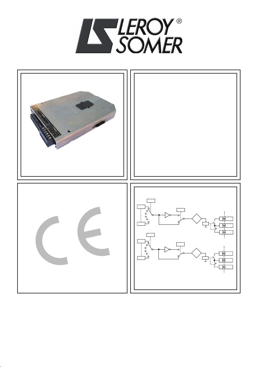
Additional Input/Output module with
Datalogger function
POWERDRIVE MD2/FX
Installation and commissioning manual
Output relay 3
1
0
Invert
Relay state
Source
RL3O
RL3C
1
2
RL3F3
RL4O
RL4C
4
5
RL4F6
19.17
19.37
19.27
Output relay 4
1
0
Invert
Relay state
Source
19.18
19.38
00.00
00.00
19.28

Installation and commissioning manual
MDX-I/O M2M
Additional Input/Output module with Datalogger function
2
5146 en - 2014.03 / a
LEROY-SOMER
NOTE
LEROY-SOMER reserves the right to modify the characteristics of its products at any time in
order to incorporate the latest technological developments. The information contained in this
document is therefore liable to be changed without notice.
CAUTION
For the user's safety, the variable speed drive to which the module covered by these instructions
is fitted, must be connected to an approved earth (terminal ).
If accidentally starting the installation is likely to cause a risk to personnel or the machines
being driven, it is essential to supply the equipment via a circuit-breaking device (power
contactor) which can be controlled via an external safety system (emergency stop, detection
of errors on the installation).
The variable speed drive is fitted with safety devices which, in the event of a fault, order it to
stop and, at the same time, stop the motor. The motor itself can become jammed for mechanical
reasons. Finally, voltage fluctuations, and in particular power cuts, may also cause the unit to
stop.
The removal of the causes of the shutdown can lead to restarting, which may be dangerous
for certain machines or installations.
In such cases, it is essential that the user takes appropriate precautions against the motor
restarting after an unscheduled stop.
The variable speed drive is designed to be able to supply a motor and the driven machine
above its rated speed.
If the motor or the machine are not mechanically designed to withstand such speeds, the user
may be exposed to serious danger resulting from their mechanical deterioration.
Before programming a high speed, it is important that the user checks that the installation can
withstand it.
The variable speed drive on which the module, covered by this manual, is fitted is designed
to be integrated in an installation or an electrical machine, and can under no circumstances
be considered to be a safety device. It is therefore the responsibility of the machine manufacturer,
the designer of the installation or the user to take all necessary precautions to ensure that the
system complies with current standards, and to provide any devices required to ensure the
safety of equipment and personnel.
Using the drive for hoisting: when using this application, it is essential to follow the special
instructions in an application-specific manual which is available on request. It is the responsibility
of the user to obtain this manual from his usual LEROY-SOMER contact.
LEROY-SOMER declines all responsibility in the event of the above recommendations
not being observed.

3
Installation and commissioning manual
MDX-I/O M2M
Additional Input/Output module with Datalogger function
5146 en - 2014.03 / a
LEROY-SOMER
SAFETY AND OPERATING INSTRUCTIONS FOR VARIABLE SPEED DRIVES
(in accordance with the low voltage directive 2006/95/EC)
• Throughout the manual this symbol
warns of consequences which may
arise from inappropriate use of the
drive, since electrical risks may lead to
material or physical damage as well as
constituting a re hazard.
1 - General
Depending on their degree of protection, the
variablespeeddrivesmaycontainunprotected
live parts, which may be moving or rotating,
as well as hot surfaces, during operation.
Unjustified removal of protection devices,
incorrect use, faulty installation or
inappropriate operation could represent a
serious risk to personnel and equipment.
For further information, consult the
documentation.
All work relating to transportation, installation,
commissioning and maintenance must be
performed by experienced, qualified
personnel (see IEC 364 or CENELEC HD
384, or DIN VDE 0100 and national
specifications for installation and accident
prevention).
In these basic safety instructions, qualified
personnel means persons competent to
install, fit, commission and operate the
product, and possessing the relevant
qualifications.
2 - Use
Variable speed drives are components
designed for integration in installations or
electrical machines.
When integrated in a machine, commissioning
must not take place until it has been verified
that the machine conforms with directive
2006/42/EC (Machinery Directive). It is also
necessary to comply with standard EN 60204,
which stipulates in particular that electrical
actuators (which include variable speed
drives) cannot be considered as circuit-
breaking devices and certainly not as isolating
switches.
Commissioning can take place only if the
requirements of the Electromagnetic
Compatibility Directive (EMC 2004/108/EC)
are met.
The variable speed drives meet the
requirements of the Low Voltage Directive
2006/95/EC. The harmonised standards of
the DIN VDE 0160 series in connection with
standard VDE 0660, part 500 and EN 60146/
VDE 0558 are also applicable.
The technical characteristics and instructions
concerning the connection conditions
specified on the nameplate and in the
documentation provided must be observed
without fail.
3 - Transportation, storage
All instructions concerning transportation,
storage and correct handling must be
observed.
The climatic conditions specified in the
technical manual must be observed.

Installation and commissioning manual
MDX-I/O M2M
Additional Input/Output module with Datalogger function
4
5146 en - 2014.03 / a
LEROY-SOMER
4 - Installation
The installation and cooling of equipment
must comply with the specications in the
documentation supplied with the product.
Variable speed drives must be protected
against any excessive stress. In particular,
there must be no damage to parts and/or
modication of the clearance between
components during transportation and
handling. Avoid touching electronic
components and contact parts.
Variable speed drives contain parts which are
sensitive to electrostatic stresses and may be
easily damaged if handled incorrectly.
Electrical components must not be exposed
to mechanical damage or destruction (risks
to health!).
5 - Electrical connection
When work is performed on variable speed
drives which are powered up, national
accident prevention regulations must be
respected.
The electrical installation must comply with
the relevant specications (for example con-
ductor cross-sections, protection via fused
circuit-breaker, connection of protective con-
ductor). More detailed information is given in
the documentation.
Instructions for an installation which meets
the requirements for electromagnetic
compatibility, such as screening, earthing,
presence of lters and correct insertion of
cables and conductors, are given in the
documentation supplied with the variable
speed drives. These instructions must be
followed in all cases, even if the variable
speed drive carries the CE mark. Adherence
to the limits given in the EMC legislation is the
responsibility of the manufacturer of the
installation or the machine.
6 - Operation
Installations which incorporate variable speed
drives must be tted with additional protection
and monitoring devices as specied in current
relevant safety regulations, such as the law
on technical equipment, accident prevention
regulations, etc. Modications to variable
speed drives using control software are
permitted.
Active parts of the device and the live power
connections must not be touched immediately
after the variable speed drive is powered
down, as the capacitors may still be charged.
In view of this, the warnings xed to the
variable speed drives must be observed.
During operation, all doors and protective
covers must be kept closed.
7 - Servicing and maintenance
Refer to the manufacturer's documentation.
This manual is to be given to the end user.

Installation and commissioning manual
MDX-I/O M2M
Additional I/O module with Datalogger function
CONTENTS
5146 en - 2014.03 / a
LEROY-SOMER
5
CONTENTS
1 - GENERAL INFORMATION ................................................................................. 6
1.1 - General ......................................................................................................................6
1.2 - Dimensions ................................................................................................................6
2 - INSTALLATION................................................................................................... 7
3 - CONNECTIONS AND CHARACTERISTICS ...................................................... 8
3.1 - Connections ...............................................................................................................8
3.2 - Characteristics ...........................................................................................................8
4 - COMMISSIONING............................................................................................. 11
4.1 - General .................................................................................................................... 11
4.2 - Diagrams..................................................................................................................12
4.3 - Explanation of parameters .......................................................................................17
5 - DATALOGGER FUNCTION .............................................................................. 32
5.1 - General ....................................................................................................................32
5.2 - Characteristics .........................................................................................................32
5.3 - Storage conguration and trigger conditions ............................................................33
5.4 - Use...........................................................................................................................34
5.5 - Datalogger function status LED................................................................................34
6 - DIAGNOSTICS.................................................................................................. 35
7 - MAINTENANCE ................................................................................................ 36

Installation and commissioning manual
MDX-I/O M2M
Additional Input/Output module with Datalogger function
GENERAL INFORMATION
6
5146 en - 2014.03 / a
LEROY-SOMER
1 - GENERAL INFORMATION
1.1 - General
The MDX-I/O M2M module is used to increase the number of drive Input/Output and also has a
Datalogger function. This option is fully congurable.
Details of functions:
- 2 analog inputs (including a differential analog input)
- 1 analog output
- 1 temperature sensor input
- 4 digital inputs
- 2 digital inputs
- 2 assignable relays
- 1 internal clock, making the date (day of the week - day of the month - month - year) and time
(hours-minutes-seconds) available in order to:
Ø Trigger actions on set dates or at set times
• Alarm for triggering maintenance (daily, weekly, monthly)
• Automation of operating cycles (Run/Stop, change of speed, change of direction of
rotation, etc.)
Ø Time-stamp an event
• Storing the day, month, year, hours, minutes and seconds of a congurable event
- Year, month, day, hours, minutes, seconds backup mode
- Web pages: an embedded Web server allows communication with the drive via an Ethernet
network (RJ45 connector)
Ø Setting the drive parameters via Web pages
Ø Downloading the drive parameters for backup
Ø Supervising the operating parameters via a congurable Web page
Ø Generating e-mails on a condition which can be congured by editing a customised text
(which can include parameter values)
- Datalogger function: used to save operating data for an extended period in order to analyse
how the machine is working without external equipment
Ø All storable drive parameters (V, A, kW, °C, etc)
Ø Sampling period congurable from 20 ms to 60 s
Ø Continuous storage or on an event
Ø Time-stamping data
Ø Data transfer to PC by .csv le via SD* card
*4 GB SD card supplied
1.2 - Dimensions
This MDX-I/O M2M option can be integrated in any product in the POWERDRIVE MD2 range.
The dimensions remain the same for drives in a cabinet.

7
Installation and commissioning manual
MDX-I/O M2M
Additional Input/Output module with Datalogger function
INSTALLATION
5146 en - 2014.03 / a
LEROY-SOMER
2 - INSTALLATION
• Before carrying out any work on the drive, disconnect and padlock the isolating
switch in the switchboard.
• After the drive is switched off, the external control circuits can retain a dangerous
amount of voltage. Check that these circuits are powered down before working on the
control cables.
• After powering down the drive, wait at least 10 min before removing the protective
plates.
• Check that the DC bus voltage is below 40 V before carrying out any work (the control
board power-on indicator LED must be off).
• Check that the module is in good condition: never insert a damaged module in the
drive.
To install the module, follow the instructions below:
1-Removetheblackplastic protective cover fromthedrivecontrolboard (connector protection).
2 - Screw the four spacers supplied with the option onto the control block (tightening torque
2 N.m).
3 - Align the option module over the drive control board connector (the optional module
connector is located on the underside of the casing) then press gently until it is fully in place.
4- Screw the module onto the control board with the four screws supplied, using a maximum
tightening torque of 2 N.m.
5- If you wish, an additional option module can be added (e.g. MDX-ENCODER). Remove the
black plastic protective cover on the MDX-I/O M2M, undo the screws inserted in step 4. Align
the additional option module over the MDX-I/O M2M board connector (the additional module
connector is located on the underside of the casing) then press gently until it is fully in place.
Then screw the module back onto the MDX-I/O M2M board using the four screws removed
earlier (2 N.m).
6 - To remove modules, follow the same procedure in reverse order.
1
5
24
Control board
Underside of
MDX-I/O M2M
option module
Control board +
MDX-I/O M2M
option module
3

Installation and commissioning manual
MDX-I/O M2M
Additional Input/Output module with Datalogger function
CONNECTIONS AND CHARACTERISTICS
8
5146 en - 2014.03 / a
LEROY-SOMER
3 - CONNECTIONS AND CHARACTERISTICS
• Check that the DC bus has discharged before any work is carried out (wait at
least 10 minutes after powering down). For the safety instructions relating to the
drive, please refer to the manual supplied with the product.
• The inputs on the POWERDRIVE MD2 and MDX-I/O M2M board have a positive logic
conguration. Using a drive with a control system which has a different control logic
may cause unwanted starting of the motor.
• The POWERDRIVE MD2 control circuit is isolated from the power circuits by single
insulation. Its electronic 0V is connected to the connection terminal on the outer
protective conductor (earth terminal). The installer must ensure that the external
control circuits are isolated against any human contact.
• If the POWERDRIVE MD2 or MDX-I/O M2M board control circuits need to be connected
to circuits conforming to SELV safety requirements, additional insulation must be
inserted to maintain the SELV classication.
3.1 - Connections
Connectors PX4 (terminals 1 to 15) and PX5 (terminals 1 to 6) are removable.
3.2 - Characteristics
• P3 connector
The P3 connector is an Ethernet port (RJ45 socket).
• PX4 connector
1- 10V ref -10V internal analog source
Voltage tolerance ± 1%
Maximum output current 10 mA continuous
Protection Current limiting: 20 mA
2AI4 + Differential analog input 4 +
3AI4 - Differential analog input 4 -
Factory setting No assignment
Input type
Bipolar voltage (differential mode and common mode)
or unipolar current (common mode only, connect
terminal 3 to the 0V)
Resolution 11 bits + sign
Sampling period 2 ms
P3 PX4 PX5
-10V ref
AI4+
AI4-
AI5
0V
AO2
DO2
DO3
0V
DI6
DI7
DI8
DI9
CTP
+24V ref
RL3 RL4

9
Installation and commissioning manual
MDX-I/O M2M
Additional Input/Output module with Datalogger function
CONNECTIONS AND CHARACTERISTICS
5146 en - 2014.03 / a
LEROY-SOMER
Voltage mode
Full scale voltage range ± 10V ± 2%
Maximum voltage 27 V
Absolute maximum voltage 33 V
Input impedance 100 kW
Current mode
Current range 0 to 20 mA ± 5%
Maximum voltage 27 V/0 V
Maximum current 50 mA
Input impedance 100 W
4AI5 Analog input 5
Factory setting No assignment
Input type ± 10 V bipolar analog voltage in common mode or
unipolar current (0 to 20 mA, 4 to 20 mA)
Resolution 11 bits + sign
Sampling period 2 ms
Input lter bandwidth ~ 200 Hz
Voltage range in common mode ± 24 V/0 V
Voltage mode
Input impedance 50 kW
Absolute maximum voltage range ± 30 V
Current mode
Input impedance 100 W
Absolute maximum current 30 mA
50V Logic circuit common 0V
6AO2 Analog output 2
Factory setting No assignment
Output type Bipolar analog voltage in common mode or unipolar
current in common mode
Resolution 13-bit
Sampling period 2 ms
Voltage mode
Voltage range ± 10 V
Load resistance 1 kW minimum
Current mode
Current range 0 to 20 mA , 4 to 20 mA
Load resistance 500 W maximum

Installation and commissioning manual
MDX-I/O M2M
Additional Input/Output module with Datalogger function
CONNECTIONS AND CHARACTERISTICS
10
5146 en - 2014.03 / a
LEROY-SOMER
7DO2 Digital output 2
8DO3 Digital output 3
Factory setting No assignment
Type Open collector
Absolute maximum voltage +30 V/0 V
Overload current 200 mA
90V 0V common
10 DI6 Digital input 6
11 DI7 Digital input 7
12 DI8 Digital input 8
13 DI9 Digital input 9
Factory setting No assignment
Type Digital inputs in positive logic
Voltage range 0 to + 24 V
Absolute maximum voltage range 0 to 35V
Thresholds 0: < 5 V
1: > 10 V
14 PTC KTY84-130 or PT100 thermal sensor
Factory setting No assignment
Sampling period 2 ms
15 + 24V ref
Output current 100 mA
Accuracy ± 5%
Protection Current limiting and setting to trip mode
• PX5 connector
1
RL3
NO relay output (RL3O)
2RL3 relay common (RL3C)
3NC relay output (RL3F)
4
RL4
NO relay output (RL4O)
5RL4 relay common (RL4C)
6NC relay output (RL4F)
Contact voltage 250 V AC
Maximum contact current 2 A, resistive load
1 A, inductive load
• Provide a fuse or overcurrent protection in the relay circuit.
Este manual sirve para los siguientes modelos
1
Tabla de contenidos
Otros manuales de Unidad de control de Leroy-Somer
Manuales populares de Unidad de control de otras marcas

Festo
Festo Compact Performance CP-FB6-E Manual de lista de piezas

Elo TouchSystems
Elo TouchSystems DMS-SA19P-EXTME Manual de usuario

JS Automation
JS Automation MPC3034A Manual de usuario

JAUDT
JAUDT SW GII 6406 Series Guía rápida

Spektrum
Spektrum Air Module System Manual de usuario

BOC Edwards
BOC Edwards Q Series Manual de usuario