LEGRAND MyHOME MHKIT4 Guía de inicio rápido

Home automation solutions
for a residential home
MyHOME® Lighting Control
and Energy Monitoring Kit – MHKIT4
Technical Guide
4.5 Zimmerwohnung 116.5 m2
0 1 3 6m
Corridor CupboardEntry
Bedroom 1
Bathroom
Bedroom 2 Bedroom 3
WC
Kitchen
Lounge
Alfresco
Dining
Room

Contents
Kit inclusions �����������������������������������������������������3
Installation configuration and placement ��������4
Kit wiring connection ����������������������������������������5
Datasheets ���������������������������������������������������������6
User Guide �����������������������������������������������������118
Warranty ����������������������������������������������������������19
The MyHOME Lighting Control and Energy
Monitoring Kit provides a solution to control
lighting circuits, switching and dimming,
and the ability to monitor energy consumption�
It includes a 3�5" colour touchscreen for
centralised management of all functions and
easy monitoring of energy consumption�
This kit comes factory pre-programmed�

23
Kit inclusions
Kit Catalogue Number: MHKIT4
MHKIT4 Contents:
■ 1 x power supply, 600mA output (Cat� No� E49)
■ 3 x trailing Edge single channel 400VA dimmer(Cat� No� F418)� To drive 3 separate
dimmer circuits (Zone 1-2-3)� Suitable for incandescent, CFL and LED fixtures†
■ 1 x double channel 6A relay per channel (Cat� No� F411/2)� To drive 2 separate lights in
the ON/OFF function (Zone 4-5)
■ 1 x 2 gang switches (Cat� No� 67552)� Controls 2 on/off lighting channels
■ 1 x 3 gang switches (Cat� No� 67554)� Controls 3 dimmer lighting channels
■ 3 x current meter (Cat� No� F520)� To monitor 3 phase power consumption of the house
■ 1 x scenario unit (Cat� No� F420) controls 16 different scenarios from the 3�5”touchscreen
■ 1 x 3�5” touchscreen (Cat� No� 573958)� Controls and monitors every single load of
automation system, plus the scenario and energy consumption
■ 1 x 24 din module enclosure box (Cat� No� HL24S)� Allows installation of all DIN devices
in a single point for easy access
Functionality of the KIT:
■ Control the dimming of your lights with a dedicated dimmer switch or the 3�5”
touchscreen
■ Switch your lights on/off using a dedicated switch or the 3�5” touchscreen
■ Use the 3�5” touchscreen as a central controller to drive the Automation system
(light-dimmer – 3 phase-energy monitoring)
■ Use a mobile device, such as a smart phone or tablet, to remotely monitor and control
the lighting, automation scenarios and your energy consumption*
*Mobile device, App and WiFi access point not included in this kit�
†Recommend using HPM or Legrand dimmable LED fixtures�
Mobile device activation
For further details on mobile setup please contact the Legrand Customer Service team
on 1300 369 777�
Warranty
Legrand 4 year extended warranty� See page 15 for details�

4.5 Zimmerwohnung 116.5 m2
0 1 3 6m
Installation configuration and placement plan
Example Zone 4 -
relay
Zone 1 -
dimmer Zone 2 -
dimmer
Zone 3 - dimmer
Zone 5 - relay

Kit wiring connection 54
Connect CAT5/CAT6 to
your home network for
smart phone app�
Panel Board
Command Switch
The dimension of the enclosure box (CAT No. HL24S) are:
330 (1)
47.5
72
350 (2)
86.5
B (2)
A (1)
125
LAN
Touchscreen
F411/2
L
N
Zone 4 & 5
PRI
SCS
E49
DEL
F420F520
C16
N L
230 Vac
F520
C16
N L
230 Vac
F520
C16
N L
230 Vac
F418
Zone 2
L
N
T1, 6H250 V
220-240V~ 50- 60 Hz
110-127V~ 50- 60 Hz
12W19
ID
200W
100W
F418
Zone 3
L
N
T1, 6H250 V
220-240V~ 50- 60 Hz
110-127V~ 50- 60 Hz
12W19
ID
200W
100W
SCS Cable
Cat. No. 336 904
Dimmer
Zone 1-2-3
Switch
Zone 4-5
F418
Zone 1
T1, 6H250 V
220-240V~ 50- 60 Hz
110-127V~ 50- 60 Hz
12W19
ID
200W
100W
L
N
L1
L2
L3

Description
Actuator for installation in DIN rail distribution boards or
switchboards� This device incorporates two independent relays
for the activation of 2 loads, and includes local control push-
buttons for each individual load, which are only active if the
actuator has been configured� The device can be installed in a
MyHOME system and configured physically or virtually� In this
case when the PL1 and PL2 positions are configured using the
same configurator the device interlocks the relays, to which it
is possible to connect motors of rolling shutters, curtains, etc�
When installed as a component of the Lighting Management
system, specific configuration procedures are used (Plug&go,
Project&Download)�
Technical features
Power supply from BUS: 27 Vdc
Operating power supply with SCS BUS: 18 - 27 Vdc
Absorption: 28 mA
Number of outputs: 2 x 6 A
Power/Absorption of driven loads:
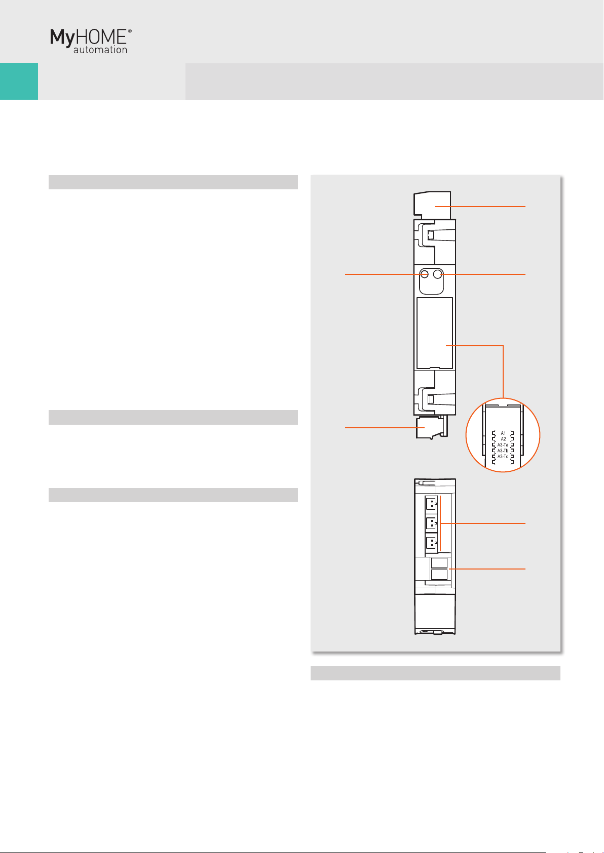
Legend
1� Configurator socket (attention, it must only be used in
MyHOME systems with physical configuration)
2� BUS
3� LED
4� Push-button
Incandescent lamps
Halogen lamp
LED lamp
Compact fluorescent lamp
230 Vac 1380 W 6 A 250 W Max. 4 lamps
Linear fluorescent lamp
Electronic transformer
Ferromagnetic
transformers
Motor reducers for
rolling shutters
230 W 1 A 2 A cosφ0.5 460 VA 460 W 2 A
Dissipated power with max load: 1�7 W(1)
Operating temperature: (-5) – (+45) ºC
Number of outputs: 2 x 6 A
NOTE: (1) The dissipated power indicated is that corresponding to the
device with all the relays loaded at the maximum load�
With lower loads also the dissipated power is lower and may be calculated
by means of the following formula: P(mW)=140+400*N+10*(Ic1+Ic2)
P: dissipated power in mW, N: no� of loaded relays, IN: load current
corresponding to the N relay�
Dimensional data
Size: 2 DIN modules
MyHOME Configuration
When installed in a MyHOME system, the device may be
configured in two ways:
■ PHYSICAL CONFIGURATION, by connecting the physical
configurators to their sockets�
■ VIRTUAL CONFIGURATION, by connecting the system to the
PC using the Kit or the Web server� The Virtual configurator
software must be installed on the PC�
C1 C2
ART. F411/2
1 2 43
1
2
3
4
Datasheets
2 relay actuator in DIN module
F411/2

67
Physical configuration
The actuator performs all the basic operating modes that can be
configured directly on the control� Moreover further operating
modes with the configurator in position M of the same actuator
are listed in the table below�
Possible function Configurator in M
Timed stop for motors� The device deacti-
vates after the time set has elapsed(1)�
This mode is only operative if LP1=LP2
(same configurators), i�e� with the two relays
interlocked
none - 9(1)
Master actuator with OFF control delayed on
the corresponding Slave actuator� With the
OFF control the Master actuator deactivates;
the Slave actuator deactivates after the time
set with the configurators has elapsed(2)�
This model is only operative if PL1≠PL2�
none - 4(2)
Actuator as Slave� Receives a control sent by
a Master actuator with the same address�
SLA
Push-button (ON monostable) ignores Room
and General controls�
PUL
2) The value of the configurator listed in the table defines the
final time, after which the actuator disables its own slave�
Configurator Time (minutes)
No configurator 1
1 2
2 5
3 10
4 infinite or until the next
control
5 20 sec
6 10 sec
7 5 sec
8 15 sec
9 30 sec
Configurator Time (minutes)
No configurator 0
1 1
2 2
3 3
4 4
Virtual configuration
Using the Virtual configurator software it is possible to perform
all the functions listed below:
■ light actuator
■ rolling shutter actuator
Lighting Management configuration
When installed in a Lighting Management system, the device can
be configured in the following ways:
■ Plug&Go (see the dedicated technical guide)
■ Project&Download,
Using the Virtual configurator software it is possible to perform
all the functions listed below:
■ Light actuator
N
L
PL
PL
M
PL
A
G1
G2
M
L1 L2
N
L
C1 C2
ART. F411/2
1 2 43 12L N
N
L
MIN 3m
3L N
4
F411/2 actuator
L1-N = clockwise rotation
L2-N = anticlockwise rotation
M = motor in AC
with 2 windings
Diagram for the control of a 230 Vac motor with 2 windings
Diagram for the connection of lighting devices
Wiring diagrams
F411/2

Datasheets
Bus meter with 3 inputs for toroids
Description
The SCS device measures currents and voltages of separate lines
(up to 3), connecting maximum three toroids to the appropriate
inputs (one toroid, item 3523 supplied as standard)�
The meter processes and saves the following variables:
■ instantaneous power in W;
■ total energy accumulated in Wh�
The device has an internal memory that allows saving the
following information:
■ cumulative energy on an hourly basis for the last 12 months;
■ cumulative energy on a daily basis for the last 2 years;
■ cumulative energy on a monthly basis for the last 12 years�
In order to allow the device to archive consumption information,
the system must be fitted with a device capable of supplying
current date and time information (e�g� Touchscreen)� If
this information is not available, the meter will be unable to
archive the data, and will continue calculating the values of the
instantaneous variables (power)� The space requirement for
the device is equal to 1 DIN module� The device is provided with
socket for 5 configurators: A1, A2, A3-Ta, A3-Tb, A3-Tc�
Technical features
Operating power supply with SCS BUS: 18 - 27 Vdc
Absorption: 35 mA max
Rated current: 16 A
Maximum current: 90 A
Operating temperature: 5 – 40 ºC
Legend
1� 230 Vac connection
2� Push-button for the deletion of cumulative energy data
3� Configurator sockets closing door
4� SCS/BUS connection
5� User interface LED, SEE TABLE
6� Ta, Tb, Tc connectors for toroids, item 3523
Dimensional data
Size: 1 DIN module
1
2
3
4
5
6
1
Front view
Top view
F520

89
Configuration
The device can be configured by connecting the physical
configurators to the correct sockets (Physical configuration)�
The device is provided with socket for five configurators:
■ A1 for the hundreds
■ A2 for the tens
■ A3 Ta for the units
■ A3 Tb for the units
■ A3 Tc for the units
The combination of the configurators defines:
■ A1/A2/A3-Ta address of meter A
■ A1/A2/A3-Tb address of meter B
■ A1/A2/A3-Tc address of meter C
The maximum number of addresses is 255�
WARNING: The A3-Ta configurator cannot be zero, differently
from configurators A3-Tb and A3-Tc, which can have a zero value
(if the corresponding input is not managed)� The meter must be
installed as close as possible to the power supply, to ensure a
high BUS voltage, and enable correct management of memory
savings in case of voltage cut� If the supply voltage is insufficient
(below 21 Vdc), the meter will cause the green LED to flash to
signal the installation error� The device will work regularly, but
will not guarantee correct saving and recovery of data in case of
BUS failure�
Procedure for the deletion of the cumulative energy data:
1 Press the key; after 20 seconds the orange LED flashes quickly;
release the key�
2 All the cumulative energy data are reset�
LED notifications based on the status of the power meter
Device status LED
Normal operation GREEN
BUS problems (BUS voltage insufficient, or
voltage drop detected)
GREEN flashing
500 ms/500 ms
Installation error (230 Vac not detected) RED flashing
100 ms/900 ms
Configuration error ORANGE flashing
irregularly on GREEN
No configuration ORANGE flashing 128
ms/128 ms on GREEN
BUS
C16
N L
Connection of the meter to the bus, the line, and the toroid
230 Vac
Wiring diagrams
F520

Datasheets
Scenario module
Description
This device allows you to manage scenarios for Automation,
Sound system and Temperature Control systems which have
been created, modified and activated using different devices of
the Automation system� Up to 16 scenarios may be saved in the
scenario module, with up to 100 controls each� The scenarios
can also give door entry and Video door entry controls for one-
family systems to switch on the staircase lights and open the
door lock� If installed in large systems with interface item F422
in logical expansion, the module can save automation controls
for the system where it is installed� On the front cover of the
item there are two keys and two LED� The first push-button
(padlock) locks or unlocks the programming procedure avoiding
involuntary operations such as cancelling the scenarios and the
corresponding LED indicates the status: green programming
possible, red programming blocked, orange temporary block�
The second push-button (DEL) cancels all the scenarios, the
LED underneath indicates that the cancellation has taken place
or that the device is performing the learning procedure�
Technical features
Power supply from SCS BUS: 27 Vdc
Operating power supply with SCS BUS: 18 - 27 Vdc
Absorption: 20 mA
Operating temperature: 0 – 40 ºC
Size: 2 DIN modules
Legend
1� Scenario cancellation push-button
2� Scenarios/learning reset LED
3� Configurator socket
4� BUS
5� Programming status LED
6� Lock/unlock programming push-button
DEL
1
2
6
4 3
5
Front view
F420
Tabla de contenidos
Otros manuales de Regulador de intensidad de LEGRAND

LEGRAND
LEGRAND 573866 Manual de usuario

LEGRAND
LEGRAND KNX modular dimmer Manual de instrucciones

LEGRAND
LEGRAND radiant WNRL50 Manual de usuario

LEGRAND
LEGRAND My Home RF Manual de usuario

LEGRAND
LEGRAND Pass & Seymour T600E Manual

LEGRAND
LEGRAND WattStopper RH703PTU Manual de usuario

LEGRAND
LEGRAND MIRO MRP6 Manual de usuario

LEGRAND
LEGRAND HKRL50 Manual de usuario

LEGRAND
LEGRAND Excel Life EM450UP Manual de usuario

LEGRAND
LEGRAND radiant WWP20CCV2 Manual de usuario


