LDG FTL-Meter Manual de usuario

PAGE 2
Table Of Contents
Introduction 3
Jumpstart, or “Real hams don’t read manuals!” 3
Specifications 4
Getting to know your FTL-Meter 4
Front Panel: 4
Back Panel: 5
Installation 6
FT-857 Installation: 6
FT-897 Installation: 7
Setup 7
Initial Calibration 7
Receive Parameter Selection 8
Transmit Parameter Selection 9
Finish Setup 9
Operation 10
Application Notes 10
Base Station Use 10
Mobile Use 10
Other Applications 10
Care and Maintenance 11
Technical Support 11
Two-Year Transferrable Warranty 11
Out Of Warranty Service 11
Returning Your Product For Service 11
Product Feedback 12

PAGE 3
INTRODUCTION
LDG pioneered the automatic, wide-range switched-L tuner in 1995. From its laboratories in St.
Leonard, Maryland, LDG continues to define the state of the art in this field with innovative automatic
tuners and related products for every amateur need.
Congratulations on selecting the LDG Electronics FTL-Meter. The FTL-Meter provides accurate and
precise metering for a wide range of receive and transmit parameters. While many users will choose to
display S-meter readings on receive, and Power Output on transmit, several other useful readings are
available.
The FTL-Meter plugs into the external meter jack on the FT-857 or FT-897 radio. Like the original FT-
Meter, the FTL-Meter is highly portable; making it ideal for DXpedition use, but the FTL-Meter provides a
much larger meter face for easier readability from even farther away.
JUMPSTART, OR “REAL HAMS DON’T READ MANUALS!”
Ok, but at least read this one section before operating the FTL-Meter:
Configure the FT-857 or FT-897 for normal operation.
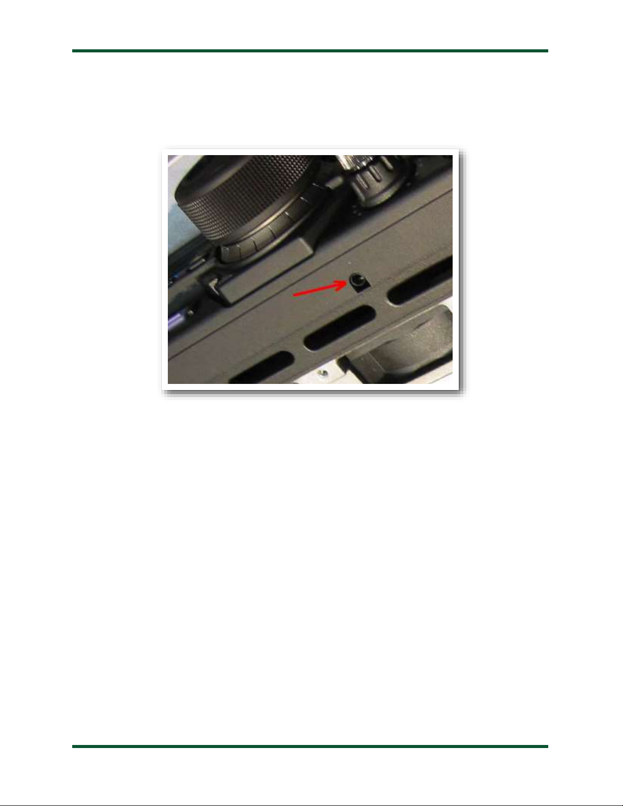
Plug the FTL-Meter into the radio’s meter jack using the right angle plug. The meter jack is on the bottom
of the front panel, under the FUNC button on the FT-857, and just to the right of the main tuning knob on
the FT-897.
Optionally, connect a 12 volt, 250mA DC power supply to the 2.5x5.5mm coaxial power jack (center
positive). This only is needed for powering the backlight; the meter will function without 12V.
Using the radio’s extended menu system, under menu items number 60 and 61, select the desired parameters
to display on the meter for receive and transmit.
Operate the radio normally; the meter will continuously display the selected receive and transmit values.
SPECIFICATIONS
•Giant, 4.75” (diagonal) 500 µA analog meter movement.
•S-meter, Discriminator, or Battery Voltage readout on receive.
•Power Output, SWR, Modulation, ALC, or Battery Voltage on transmit.
•Externally powered cool blue backlighting with adjustable brightness.
•On/Off switch for backlight.
•Backlight requires 12VDC, 250mA. 2.5 x 5.5mm jack, center positive.
•Power cable and RAM (radio interface) cable included.
•Dimensions: 5.25”L x 4”W x 4.25”H
•Weight: 1 pound

PAGE 4
GETTING TO KNOW YOUR FTL-METER
Your FTL-Meter is a quality, precision instrument that will give you many years of outstanding service;
take a few minutes to get to know it.
Front Panel:
The front panel of the FTL-Meter shows seven calibrated scales:
S: Received signal strength
ALC: Automatic Level Control voltage, on transmit. Shares the S-meter scale.
PWR: Transmit power output in watts
SWR: Transmit Standing Wave Ratio
MOD: Transmit modulation percentage
VOLT: Battery voltage, in transmit or receive
DISC: FM discriminator reading on receive
The FTL-Meter displays different scales on receive and transmit. Selection of which scales is made in
the radio’s setup menu. There are no controls on the FTL-Meter; operation is fully automatic.

PAGE 5
Back Panel:
The rear panel of the FTL-Meter has two jacks, a rocker switch, and two access holes for adjustments.
The DC Coax jack accepts a 2.5 x 5.5mm coaxial DC power cable, 12V, 250mA, center positive.
External power is only required if use of the internal backlight is desired. The meter functions correctly
otherwise without it.
The jack marked “Radio” accepts an 1/8” stereo plug, the other end of which plugs into the meter jack
on the FT-857 or FT-897. If desired, a standard headphone extension cable may be used to place the FTL-
Meter farther from the radio.
The rocker switch is used to turn the internal backlight on and off. It may be desirable to turn off the
internal backlight when attempting to conserve battery power.
The brightness of the backlight may be adjusted with a small flat blade screwdriver. Carefully insert the
screwdriver into the hole labeled “Brightness”, and gently turn the potentiometer left or right until the
desired brightness is achieved.
The full-scale reading may be adjusted by turning the potentiometer marked “FS” on the rear of the
meter. See the section on Calibration for details.
Installation:
The FTL-Meter is intended for indoor use only; it is not water-resistant. If you use it outdoors, (QSO
Party outdoor barbecue, for example) you must protect it from rain.
Place the FTL-Meter in a convenient location near the FT-857 or FT-897. The included cable has a six
foot reach.

PAGE 6
FT-857 Installation:
The meter jack on the FT-857 is located under the front panel, near the FUNC button. Plug the right-
angle end of the included 1/8” stereo cable into the meter jack. Plug the other end of the cable into the jack
marked “Radio” on the rear of the FTL-Meter.
If desired, connect a suitable power supply (12VDC @ 250mA) to the DC Power jack on the rear of the
FTL-Meter, using the supplied 2.5 x 5.5mm center-positive power cable. This power connection supplies
power to the backlight only. If the backlight feature is not desired, simply leave the DC power unconnected,
and the meter will still function normally.

PAGE 7
FT-897 Installation:
The meter jack on the FT-897 is located under the front panel, just to the right of the main tuning knob.
Plug the right-angle end of the included 1/8” stereo cable into the meter jack. Plug the other end of the
cable into the jack marked “Radio” on the rear of the FTL-Meter.
If desired, connect a suitable power supply (12VDC @ 250mA) to the DC Power jack on the rear of the
FTL-Meter, using the supplied 2.5 x 5.5mm center-positive power cable. This power connection supplies
power to the backlight only. If the backlight feature is not desired, simply leave the DC power unconnected,
and the meter will still function normally.
SETUP
Yaesu included two menu items in the extended menu system of the FT-857 and FT-897 transceivers, to
allow configuring an external meter such as the FTL-Meter. In order to access those menu items, first, the
extended menu system must be enabled if it is not already.
Press and hold the FUNC button on the transceiver to enter menu mode. Rotate the SELECT knob
until menu 1, “EXT MENU” is showing. Turn the main tuning knob until EXT MENU is “ON”. This
enables the extended menu system.
Initial Calibration
As shipped from the factory, the FTL-Meter is calibrated, but may require some adjustment due to
shipping or other factors. When the radio is off, the needle on the FTL-Meter should rest at the “1:1” line
on the SWR scale. If it does not, insert a flat blade screwdriver into the plastic screwhead under the meter
face on the front panel of the FTL-Meter. Gently turn the screw in either direction until the needle rests on
1:1.

PAGE 8
Next, the full scale reading of the meter should be calibrated. With the transceiver turned on, enter
menu mode, and rotate the SELECT knob until menu item 60 “MTR ARX SEL” is showing. Now rotate
the main tuning knob until “FS” is displayed. This tells the transceiver to output a full-scale reading signal
on the meter jack, for calibration. Verify that the needle is now resting on the very right-hand edge of the
red portion of the S-meter scale, just to the right of the +60 mark.
If the full scale reading requires adjustment, insert a small flat blade screwdriver into the hole marked
“FS” on the rear of the FTL-Meter, and turn the potentiometer gently left or right until the needle is exactly
in the correct position on the meter.
The meter is now calibrated, and further calibration should not be necessary.
Receive Parameter Selection
With the transceiver still in menu mode, on menu #60, “MTR ARX SEL”, rotate the main tuning knob
to choose which radio parameter is displayed on the FTL-Meter during receive operation. There are four
options from which to choose:
Menu #60 MTR
ARX SEL
Meaning
OFF
No meter display when receiving
VLT
Displays incoming power supply voltage
CTR
FM discriminator centering. FM reception is tuned
properly when the needle is in the center.
SIG
Received signal strength (S-Meter)
Select the desired parameter that will be displayed when the transceiver is in receive mode.

PAGE 9
Transmit Parameter Selection
With the transceiver still in menu mode, turn the SELECT knob until menu item #61, “MTR ATX
SEL” is displayed. This menu selects what value is displayed on the meter during transmit operation. Rotate
the main tuning knob to select one of the following 6 options:
Menu #61 MTR ATX
SEL
Meaning
OFF
No meter display when receiving
VLT
Displays incoming power supply voltage
SWR
Standing Wave Ratio (SWR)
MOD
Modulation percentage / deviation level
ALC
Automatic Level Control voltage
PWR
Transmit power output
Select the desired function to display.
Finish Setup
When finished with selecting receive and transmit parameters, press and hold the FUNC button to
return the radio to normal operation. If, at some point, it is desired to display different parameters, the
parameter selection process can be repeated. Just select menu item 60 for the receive parameter, or menu
item 61 for the transmit parameter.

PAGE 10
Operation
Operation of the FTL-Meter is completely transparent. There are no controls, and no user input is
required. Simply operate the transceiver as usual, and the FTL-Meter will display the selected parameters
during transmit and receive operation. If the display of different parameters is desired, simply repeat the
Receive Parameter Selection or Transmit Parameter Selection as required.
APPLICATION NOTES
Base Station Use
The FTL-Meter may be placed nearly anywhere on the operating desk. The included 1/8” stereo
connection cable provides the ability to place the meter up to several feet away from the transceiver. Some
obvious choices include on top or beside the radio, or near the station computer.
Mobile Use
The FTL-Meter is ideal for mobile operation. As the FTL-Meter is a bit larger than its smaller cousin,
use of Velcro to mount the meter to the dashboard is not recommended.
If using the FTL-Meter in a mobile application, LDG recommends that a fused power cable (not
included) is used to power the FTL-Meter. A 1 amp “fast-blow” fuse is recommended.
Remember to keep your eyes on the road, and not on the giant FTL-Meter’s meter face!
Other Applications
LDG designed your FT-Meter specifically for the Yaesu FT-857 and FT-897 transceivers, and does not
recommend using it in any other application. However, the meter is, in fact, simply a 500 micro-amp meter
movement; the calibration potentiometer allows a range of .5 - 2 mA. If you choose to use it in a different
application, take care not to exceed the maximum current specification; the meter movement will be
damaged or destroyed by current in excess of this specification.
Tabla de contenidos
Otros manuales de Instrumento de medición de LDG

LDG
LDG TW-1 Manual de usuario

LDG
LDG TW-1 Manual de usuario

LDG
LDG TW-2 Manual de usuario

LDG
LDG M-7700 Manual de usuario

LDG
LDG FT-meter Manual de usuario

LDG
LDG M-600 Manual de usuario

LDG
LDG MC-101 Manual de usuario

LDG
LDG MC-7600 Manual de usuario

LDG
LDG M-1000 Manual de usuario

LDG
LDG M-7600 Manual de usuario
Manuales populares de Instrumento de medición de otras marcas

Endress+Hauser
Endress+Hauser Proline Promag 50 Especificaciones técnicas

Siemens
Siemens SITRANS F Coriolis FCT030 Manual de lista de piezas

KLINGER
KLINGER CMF V Series Manual de usuario

EXFO
EXFO FTB-2 Manual de operación y mantenimiento

Keysight
Keysight M8290A Manual de usuario

ADTEK
ADTEK MW-5 Manual de usuario


