LAUREL LTS Manual de usuario

Model LTS
RS232 OR RS485 SERIAL INPUT,
ANALOG OUTPUT TRANSMITTER
Modbus or Custom ASCII Proto ol
OWNERS MANUAL
LAUREL Electronics Inc.
3183-G Airway Ave, Costa Mesa, CA, 92626, USA
el: (714) 434-6131 Fax: (714) 434-3766 • Website: www.laurels.com

- 2 -
1. ORDERING GUIDE, SERIAL INPUT TRANSMITTER
Configure a model number in this format: LTS60, CBL04
LTS
6
…Transmitter with 4-20 mA, 0-20 mA,
0-10V
or
-10V
to
+10V isolated analog
out ut, RS232 or RS485 serial data
in ut, and dual 120 mA solid state
relays. Default jum ered for RS232.
LTSE6E… Transmitter with 4-20 mA, 0-20
mA, 0-10V or -10V to +10V isolated
analog out ut, Ethernet serial data
in ut, and dual 120 mA solid state
relays.
Power
0............................. 85-264 Vac or 90-300 Vdc
1................................. 12-30 Vac or 10-
48 Vdc
ACCESSORIES
CBL04……RS232 cable, two 3- in connec-
tors on transmitter end, DB9
connector on com uter end.
CBL02……USB to DB9 ada ter cable. Can
be used with CBL01 or CBL04.

- 3 -
2. TABLE OF CONTENTS
1. ORDERING GUIDE, SERIAL INPUT TRANSMITTER .......................................................... 2
2. TABLE OF CONTENTS ....................................................................................................... 3
3. INTRODUCTION, SERIAL INPUT TRANSMITTER .............................................................. 4
4. RECEIVING & UNPACKING YOUR TRANSMITTER ........................................................... 5
5. SAFETY CONSIDERATIONS .............................................................................................. 6
6. TRANSMITTER FIELD WIRING ......................................................................................... 7
7. JUMPER SETTINGS .......................................................................................................... 8
8. PROGRAMMING YOUR TRANSMITTER ............................................................................ 10
9. LTS STREAMING DATA INPUT MODE WITH CUSTOM ASCII PROTOCOL ........................ 12
10. LTS COMMAND MODE WITH CUSTOM ASCII PROTOCOL ............................................... 21
11. LTS COMMAND MODE WITH MODBUS RTU PROTOCOL ................................................ 22
12. USING DIAGNOSTIC TOO QMODMASTER ........................................................................ 23
13. SPECIFICATIONS, LTS SERIAL INPUT TRANSMITTER ..................................................... 27
14. WARRANTY ...................................................................................................................... 28

- 4 -
3. INTRODUCTION, RS232 OR RS485 SERIAL INPUT TRANSMITTER
The LTS seri l input to n log output tr nsmitter (or serial-to-analog converter) acce ts
numeric readings embedded in streaming RS232 or RS485 ASCII serial data, and converts
these to an isolated, scalable 4-20 mA, 0-20 mA, 0-10V or -10V to +10V analog out ut. It also
acce ts Modbus RTU or Custom ASCII rotocol commands to out ut a s ecific current or
voltage. The unit fits on a 35 mm DIN rail and is only 22.5 mm (0.89") thick. Model LTS60 can
be owered by 85-264 Vac AC line voltage. Model LTS61 can be owered by low voltage AC or
DC, like 24 Vdc. All electrical connections are via detachable screw-clam lugs. LTS models
use an LT counter transmitter board, but no signal conditioner board. LT counters with a signal
conditioner board, like model LT60FR, can also be used for serial to analog conversion.
The current or volt ge tr nsmitter output is jum er selectable and is transformer isolated to
avoid ground loo s. Either out ut rovides 16-bit resolution of the out ut s an and is ultra-
linear to within one bit. The out ut is scaled to the serial in ut in software. Rated accuracy is
±0.02% of s an.
Du l solid st te rel ys rated 120 mA at 140 Vac or 180 Vdc are standard. The relays can
res ond to the transmitted serial values or to transmitted control characters, which override the
internal set oints. The relays can also be controlled inde endently of the serial in ut by
a lying signals to control in uts 1 and 2.
Isol tion to 250V rms is rovided for ower, the serial data in ut, analog out ut, and relay
out uts. Isolation adds safety and avoids ossible ground loo s.
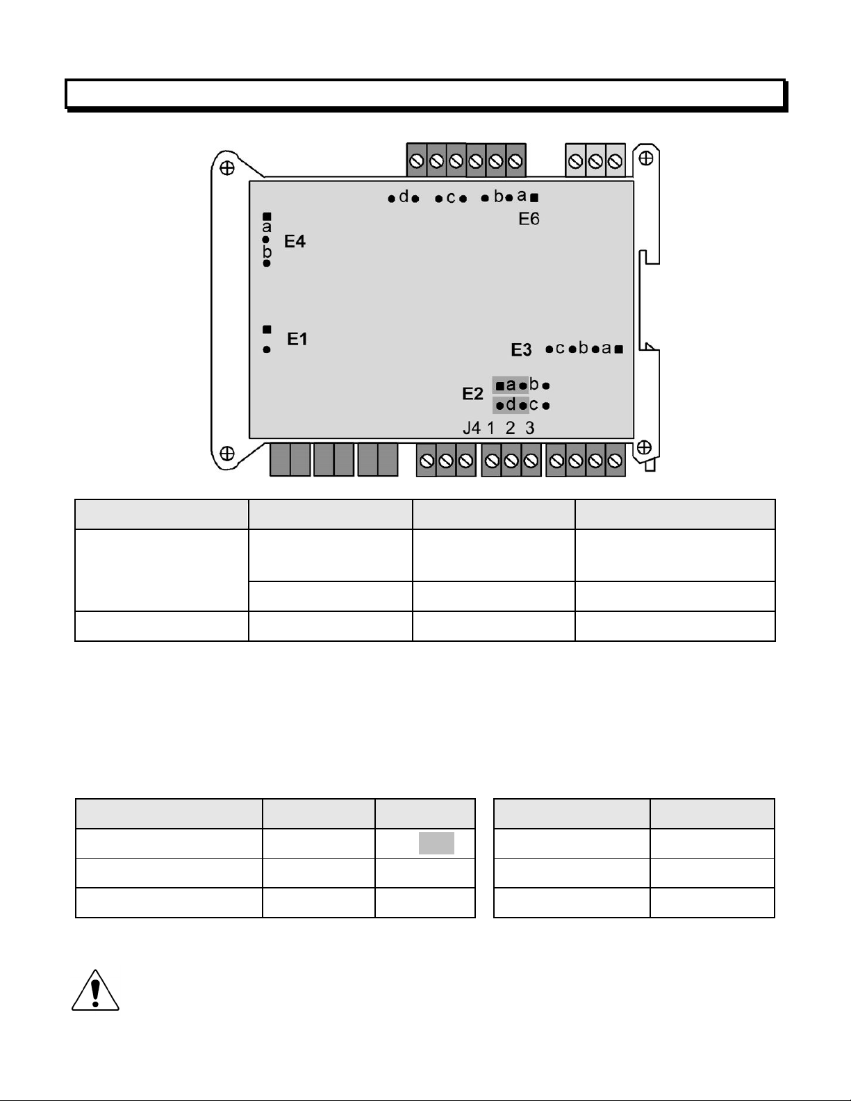
Seri l d t input selections are RS232, half-du lex RS485, or full-du lex RS485. Selection is
via jum ers and/or at the connector.
Tr nsmitter setup is via the unit’s serial ort using an external PC and Instrument Setu
software, which can be downloaded from our website at no charge. The required 3-wire
transmitter-to-PC interface RS232 cable (CBL04) is easy to build and is also available for
urchase. Plugging cable CBL04 into a CBL02 RS232-to-USB converter cable allows the LTS
unit to be rogrammed via the USB ort of a PC.
The LTS is not plug nd pl y. The format of the strings being received must be known in
advance, including non- rinting control characters. If you do not know the format of your ASCII
data, contact tech su ort of the manufacturer of the sending device. Or use a terminal
emulator PC rogram, like HyperTermin l, PuTTY, or Re lTerm, to view the received data on
your PC.
The LTSE6 Ethernet input to n log output tr nsmitter acce ts streaming Ethernet data and
converts it to an isolated, scalable 4-20 mA, 0-20 mA, 0-10V or -10V to +10V analog out ut.
That transmitter is covered by a se arate user manual.

- 5 -
4. RECEIVING & UNPACKING YOUR TRANSMITTER
Your transmitter was carefully tested and ins ected rior to shi ment. Should the transmitter be
damaged in shi ment, notify the freight carrier immediately. In the event the transmitter is not
configured as ordered or is ino erable, return it to the lace of urchase for re air or re lacement.
Please include a detailed descri tion of the roblem.

- 6 -
5. SAFETY CONSIDERATIONS
W rning: Use of this transmitter in a manner other than s ecified may im air the rotection
of the device and subject the user to a hazard. Visually ins ect the unit for signs of damage. If the
unit is damaged, do not attem t to o erate.
C ution:
• This unit may be owered with AC (mains) from 85-264 Vac or 90-300 Vdc with the high
voltage ower su ly o tion, or 12-30 Vac or 10-48 Vdc with the low voltage ower su ly
o tion. Verify that the ro er ower o tion is installed for the ower to be used. This
transmitter has no AC (mains) switch. It will be in o eration as soon as ower is a lied.
• The 85-264 Vac or 90-300 Vdc mains connector (P1 Pins 1-3) of model LTS60 is colored
green to differentiate it from other in ut and out ut connectors. The 12-30 Vac or 10-48 Vdc
mains connector of model LTS61 is colored bl ck.
• The analog out ut is sourcing. Do not connect the 4-20 mA analog out ut to a load designed
to a ly 24 Vdc to a two-wire transmitter. A lying 24 Vdc will burn out the main board.
• To avoid dangers of electrocution and/or short circuit, do not attem t to o en the case while
the unit is under ower. However, signal wiring changes external to the case can be made
safely while the unit is under ower.
• To revent electrical or fire hazard, do not ex ose the transmitter to excessive moisture.
• Do not o erate the transmitter in the resence of flammable gases or fumes. Such an environ-
ment constitutes an ex losion hazard.
• Secure the transmitter to a 35 mm DIN rail.
Symbols used:
Caution (refer to accom anying
documents)
Caution, risk of electric shock.
Equi ment rotected throughout
by double insulation or reinforced
insulation.
Earth (ground) terminal.
Both direct and alternating current.
Oper ting environment:
• Class II (double insulated) equi ment
designed for use in Pollution degree 2.
PROVISION FOR COOLING
PROVISION FOR COOLINGPROVISION FOR COOLING
PROVISION FOR COOLING
AL 1
AL 2
RESET
POWER
AL 1
AL 2
RESET
POWER
AL 1
AL 2
RESET
POWER
AL 1
AL 2
RESET
POWER
AL 1
AL 2
RESET
POWER
To avoid overheating, mount transmitters
with ventilation holes at t
o and bottom.
Leave a minimum of 6 mm 1/4”
) between
transmitters, or force air with a fan.

- 7 -
6. TRANSMITTER FIELD WIRING

- 8 -
7. JUMPER SETTINGS
Seri l Sign l
Duplex
Jumpers
Termin tion Resistor*
RS485 Full None E6 a = Transmit
E6 c = Receive
Half E6 b + d** E6 c
RS232 Full None None
* The termination resistor jum er settings should only be selected if the transmitter is the last
device on an RS485 line longer than 200 feet (60 m).
** Or connect external BTX to BRX and ATX to ARX (same effect as internal jum ers).
To reset communic tions to 9600 baud, command mode, Custom ASCII rotocol, and Address 1,
lace a jum er at E1, cycle ower, remove the jum er, and restart the transmitter.
An log Output
J4 Pins
Jumpers
Current, 4-20 mA 1 Lo, 2 Hi E2 a + d
Voltage, 0-10V 1 Lo, 2 Hi E2 b + c
Voltage, -10V to +10V 3 Lo, 2 Hi E2 b + c
Excit
tio
n Ou
tput
Jumpers
5V, 100 mA E3 a + c; E4 a
10V, 120 mA E3 a + c; E4 b
24V, 50 mA E3 b, E4 none
Notes:
Notes:Notes:
Notes: 1.
1.1.
1. Jum ers for 4-20 mA out ut are shaded. Jum er settings are for main board Rev J.
2.
2.2.
2. Attem ting to draw more than rated excitation out ut current will shut down the out ut.
3.
3.3.
3. The n log output is sourcing. Do not a ly an external voltage. A lying an external
voltage of 24 Vdc will burn out the transmitter main board.

- 9 -
WHEN TO CHANGE JUMPERS
Your transmitter case does not need to be o ened if jum ers have already been set by your
distributor. Otherwise you will need to o en the case and either set jum ers or verify that the
factory default jum ers ositions will meet your needs. Factory default jum er settings are for
RS232 in ut and 4-20 mA out ut.
HOW TO OPEN & CLOSE THE CASE
The two clamshell halves of the case are held together with a bolt and a nut at each of the four
corners. Use a Philli s screwdriver to remove the four bolts. The nut will then dro off, and the
clamshell halves will se arate. When closing the case, make sure that the ventilation grills are
ro erly aligned.
C ution: The nuts at each corner are not ca tive and are black. Take recautions
so that the nuts do not get lost.

- 10 -
8. PROGRAMMING YOUR TRANSMITTER
OVERVIEW
LTS serial in ut transmitters are rogrammed using a PC with a USB ort and our free Instru-
ment Setu (IS) software, which rovides a gra hical user interface. This software allows
u loading, editing, downloading and saving of setu data. To interface the LTS to the PC, two
cables are lugged into each other: CBL04, a three-wire cable which connects the RS232 ort
of the LTS unit to a DB9 connector, and CBL02, an RS232-to-USB ada ter cable which con-
nects the DB9 connector to the USB ort of the PC. CBL02 incor orates and FTDI chi which is
com atible with all versions of MS Windows.
USING INSTRUMENT SETUP (IS) SOFTWARE
As a first ste , set User Account Control (UAC) of your version of Windows to "Never notify" so
that Instrument Setu Software can create directories. Use Google for instructions. Power
down and restart your com uter for the UAC change to take effect. Download the file
ISx_x_x.exe from our website and double-click on the file name. Click on “Install Instrument
Setu Software” and follow the rom ts. To launch IS software, ress on Start => Programs =>
IS2 => Instrument Setu or on the deskto icon that you may have created. Following a brief
s lash screen, the Communications Setu screen below will a ear.
Este manual sirve para los siguientes modelos
2
Tabla de contenidos
Otros manuales de Transmisor de LAUREL
Manuales populares de Transmisor de otras marcas

Dejero
Dejero EnGo 3x Manual de usuario

Rosemount
Rosemount 4600 Manual de usuario

Speaka Professional
Speaka Professional 2342740 Manual de usuario

trubomat
trubomat GAB 1000 Manual de usuario

Teledyne Analytical Instruments
Teledyne Analytical Instruments LXT-380 Manual de usuario

Rondish
Rondish UT-11 Manual de usuario


