Kutzner + Weber MUC Manual de usuario

KUTZNER +WEBER
MUC Multi Use Controller
INSTALLATION INSTRUCTIONS

MUCIOM
2|Page
Contents
1. Introduction 3
2. Specifications 4
3. Component List 5
4. Installation 6
a. Mounting 6
b. Electrical 7
c. Battery Installation and Removal 9
d. GFS Differential Air Pressure Switch
Exhaust Applications (GF/ GH)
10
e. CS75 Current Switch
Supply Air System (SA)
13
e. GFS Differential Air Pressure Switch
Supply Air System (SA)
15
5. Operation 19
a. Modes 19
b. Inputs and Outputs 22
c. Flow Chart 24
c. Troubleshooting 25
6. Reference List 26

MUCIOM
3|Page
Multi Use Controller (MUC) IOM
Installation, Operation and Maintenance Manual
Please read and save these instructions for future reference. The proper installation and
maintenance of this unit will allow the unit to deliver years of dependable service. Read
carefully before attempting to assemble, install, operate or maintain the product
described. Protect yourself and others by observing all safety information. Failure to
comply with instructions could result in personal injury and/or property damage!
Installation and maintenance are to be performed only by qualified personnel who are
familiar with local codes and regulations and who are experienced with this type of
equipment. Personnel should have a clear understanding of these instructions and
should be aware of general safety precautions.
DANGER! Always disconnect, lock and tag power source before installing or servicing.
Failure to disconnect power source can result in fire, shock or serious injury.
CAUTION! Consult and follow all applicable national, state and local codes. They will
supersede this document.
WARNING! No installation, use or maintenance should be done in an explosive or
hazardous environment.
Introduction
The Multi Use Controller (MUC) is an intelligent easy to install wall mounted device that
is a constant speed controller used to safely exhaust or provide supply air to gas or
solid fuel fired fireplaces and heating appliances. Designed for use with electronically
commutated motors (ECM), the MUC meets all code requirements for NFPA211,
NFPA54, IFGC2012, IMC2012 and UMC2012
Features include:
User control via Integrated slide switch 0-10 VDC potentiometer to control a draft
inducer or power venter
Enable input for remote operation
Code compliant safety mechanism designed for ECM fault protection
Visual and audible alarm if the controller detects a problem with the fan
Includes an integrated safety function to verify the pressure is negative or if the
motor is functioning properly as required per national and local codes
Device status indicators via a green LED and red LED as well as an audio
buzzer that can be muted
Includes a battery back-up if the control loses power
Note: Information contained within this manual may be updated without notice.

MUCIOM
4|Page
Specifications
Power Supply 24 VDC (non-isolated half-wave rectified)
Consumption 32 mA max @ 24 VDC (Run Mode)
Protection Circuitry Reverse voltage protected, overvoltage protected
Operating Conditions 4-32 C (40-90 F), 20-80 %RH non-condensing
Wiring Connections Screw terminal block (14 to 22 AWG)
Enclosure Wall mount enclosure, 3.3”w x 4.7”h x 1.15”d
(84 x 119 x 29 mm)
Relay Output Contact Ratings Form C contact (N.O. + N.C.), 5 Amps @ 250 VAC, 5
Amps @ 30 VDC
Slide Potentiometer Front panel pot is two-wire resistive output,
0-10 K standard
Analog Output 0-10 VDC
Audio Mute Switch Front panel push-button dry contact
LEDs Red LED =Super Bright, Low Current,
Green LED =Super Bright, Low Current
Audio Buzzer 3V, 2700 Hz +/- 200 Hz, SPL = 80 dBA
Back Up Battery 2 x CR2032 Lithium-Manganese Dioxide Coin Cells, 3V,
220 mAH, 3.0 x 20.0 x 20.0 mm

MUCIOM
5|Page
Component List
The MUC system is made up of several components dependent on the application:
1. MUC Controller
2. System Application Components
a. GF : gas fireplace system
i. Draft inducer / vent fan
1. VFD included with induction motors
ii. GFS: differential air pressure switch
iii. Vent probe and tubing
iv. Power supply (24 VDC)
b. GH : gas heating appliance system
i. Draft inducer / vent fan
1. VFD included with induction motors
ii. GFS: differential air pressure switch
iii. Vent probe and tubing
iv. Power supply (24 VDC)
c. SA : supply air system
i. Supply fan
ii. CS75 current switch
iii. Power supply (24 VDC)
d. SF : solid fuel fireplace system
i. Draft inducer / vent fan
ii. Power supply (24 VDC)
3. Optional / Additional Components
a. CO detector
b. GFS: differential air pressure switch
c. Spill switch kit(s)
d. XB expansion board

MUCIOM
6|Page
Installation of the MUC
Before Installation
Read these instructions carefully before installing and commissioning the device.
Failure to follow these instructions may result in product damage. Do not use in an
explosive or hazardous environment, with combustible or flammable gases, as a
safety or emergency stop device or in any other application where failure of the product
could result in personal injury. Take electrostatic discharge precautions during
installation and do not exceed the device ratings.
Mounting
The Multi Use Controller (MUC) installs directly on a standard electrical box. The cover
is hooked to the base at the top edge and must be removed from the bottom edge first.
Use a small screwdriver to carefully pry each bottom corner if necessary. If a security
screw is installed on the bottom edge, then it may have to be loosened or removed also.
Tip the cover away from the base and set it aside.
The MUC must be removed from the base to access the mounting holes. Follow normal
anti-static procedures when handling the MUC and be careful not to damage any
components. The MUC is removed by pressing the enclosure base to unsnap the latch
near the bottom edge, then the MUC can be lifted out of the base. Sit the MUC aside
until the base is mounted.
After the base is screwed to an electrical box
or the wall using the appropriate holes, pull
the wires through the wiring hole in the center
of the MUC and then reinstall it in the
enclosure base. Ensure the MUC is snapped
into the base securely and correctly.
The mounting hole locations are shown on
figure 1:
Figure 1

MUCIOM
7|Page
Electrical
The MUC may be wired for different applications. Review the supplied wiring diagram(s)
and verify the application before attempting to connect the MUC to any associated
components or equipment. Follow all local electrical and safety codes, as well as the
National Electrical Code (NEC) and the National Fire Protection Agency (NFPA), where
applicable. Follow the Canadian Electric Code (CEC) in Canada.
Note: Use 18 AWG shielded wire for all low voltage connections. Do not locate the
device wires in the same conduit with high voltage wiring or used to supply
inductive loads such as motors.
Disconnect the power supply before making any connections to prevent electrical shock
or equipment damage. Follow proper electrostatic discharge (ESD) handling procedures
when installing the device or equipment damage may occur.
24 VDC From GFS Pressure Switch
24 V
To Fan Motor Speed Input
Dampe
r
Relay
ENABLE
Gas
Relay
Green LED (RUN)
Red LED (Fail)
Battery Tray
A
udio Mute Switch
A
udio Buzze
r
Slide Control Potentiomete
r
Cut Out
COM
POT
MSTAT
Dampe
r
Gas
COM
COM
N.C.
N.C.
N.O.
N.O.
24 VDC From Remote Unit
Common
24 VDC From Power Supply
BATT
ON
OFF
Battery Enable Jumper Select
RPM BYPASS Enable
Jumper Select
PROVER
+5V
RPM
Motor Status Feedback Voltage
5 VDC To Moto
r
Motor RPM Feedback Signal
RPM BYPASS
ONOFF
Figure 2

MUCIOM
8|Page
Power Connections
The MUC requires a 24 VDC power supply to operate. The device has a half-wave type
power supply so the power supply common is the same as the output signal common.
Several devices may be connected to one power supply and share the same signal
common.
Use caution when grounding the secondary of a power supply or when wiring multiple
devices. Ensure that the circuit ground points are the same on all devices.
Connect the positive DC voltage to the 24V terminal and the power supply common to
the COM terminal. The device is reverse voltage protected and will not operate if the
power supply is connected backwards.
Note: the COM terminal is NOT connected to the Relay COM terminals.
Heating Appliance Connections
Refer to the appliance manufacturer's instructions or contact the appliance
manufacture for specific connections within the appliance.
Enable Input (remote operation)
Many appliances have a dry contact to enable external devices (louvers, pumps, etc.)
built into the appliance control system. Those that don't may require a relay to be field
installed within the appliance to provide the necessary dry contact for the Enable
(remote) signal to the MUC.
Note: Install a jumper between 24V to ENABLE when remote operation is not required
Relay Wiring
The MUC relay outputs are completely isolated. The gas and damper relays each have
their own 3 terminal connection block, each with a COM, N.O. (Normally Open) contact
and N.C. (Normally Closed) contact. Connect the gas valve and damper relay
connections as per the labeled terminal blocks for each as illustrated in the system
wiring diagrams for the N.O. (normally Open) contact operational control.
The gas relay is the interlock for enabling the heating appliance or gas log set
when all the safety and run conditions are proven
The damper relay is for enabling an external device such as a damper or VFD
when the MUC is enabled to run
Motor Connections
Connect the fan motor as per the supplied system diagram for the motor type.

MUCIOM
9|Page
Battery Insertion and Removal
After the MUC has been wired completely into the system insert the backup
battery tray into its holder on the MUC.
When normal operating power is provided to the MUC the device will enter normal
operating mode and exit back up mode.
To insert the backup batteries into the MUC simply slide and push the battery tray into
the battery holder on the MUC as illustrated in figure 3, ensuring that the positive
terminal is facing upwards. To remove the battery tray from the battery holder on the
MUC simply push on either the bottom or top battery tray tab to pop the tray slightly out
from the battery holder on the MUC and then pull the tray out from the battery holder as
illustrated in figure 3.
Battery Removal
1. Push either tab to pop battery tray
slightly out
2. Then slide tray out from holder
Battery Holder with inserted
battery tray
Battery Holder
Battery Tray
1. Push and slide battery tray into
holder
Battery Insertion
Figure 3
MUCIOM
10|Page
GFS Differential Air Pressure Switch Installation
Systems with a gas heating appliance or gas log set require a GFS differential air
pressure switch to prove fan function and available draft in the venting system.
Mounting
Check the pressure switch for damages. Do not use if damaged! Do not mount the
pressure switch on uneven, hot, or vibrating surfaces! Do not tighten the screws too
much, in order to avoid deforming of the device’s base. Mount the pressure switch with
the pressure connections pointing downwards, to drain condensation moisture which
might occur. In general, the mounting with two screws next to each other is sufficient.
The maximum diameter of the screws must not be bigger than 0.315" (8 mm).
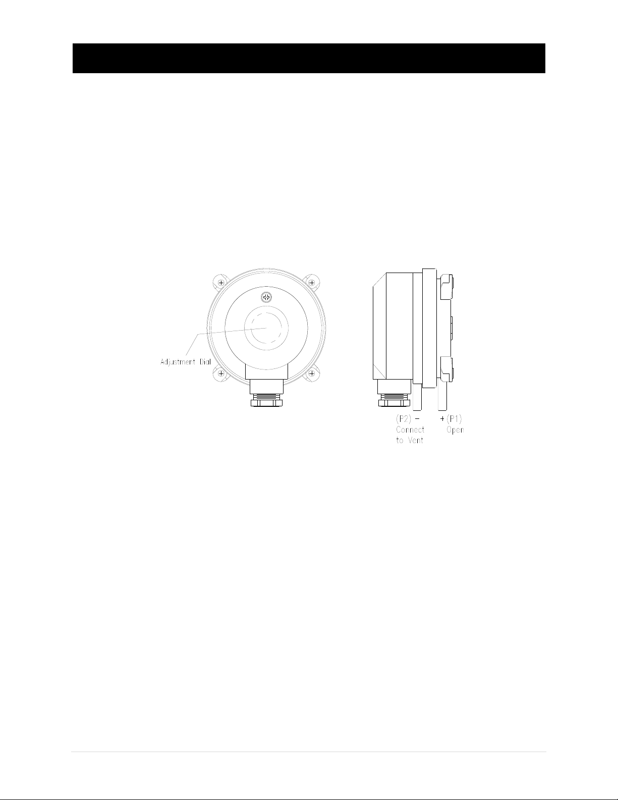
Pneumatic Connections
The two pressure ports on the end of the enclosure are labeled P1(+) and P2(-). Ensure
these ports are connected correctly and that the shipping cap is removed from port(s).
Install the vent probe as close to the fan as possible on a fireplace system, figure 5. On
a gas heating appliance vent system install the vent probe in the common, figure 6.
Then connect the pressure tubing between the vent probe and the P2(-) port on the
GFS pressure switch. Use the supplied high temperature 0.170” I.D. flexible tubing for
the pressure connections.
If mounting location is farther than 10ft use 0.25" I.D. rigid tubing. Cut 2 short pieces of
the supplied tubing and use as couplings for proper sealing, heat isolation and ease
of installation. Arrange the tubing to minimize stress on the connections and ensure
there are no kinks in the tubing. In vent systems it is recommended that the tubing slope
back to the vent for draining to prevent condensate from collecting in the sensing line.
Ensure the tubing is clean and do not allow material to fall into the pressure ports as
contamination could damage the switching mechanism. When removing tubing use care
to avoid breaking the ports.
Figure 4
Tabla de contenidos
Otros manuales de Controladores de Kutzner + Weber


