
Kallipr Captis Pulse Lite 1.0 Manual de usuario

Captis Termination Guide
12/12/2022

Captis Cloud Configuration Guide Page | 1
Contents
1Scope............................................................................................................................................................................2
2Before You Begin ......................................................................................................................................................2
2.1 What do you need? ........................................................................................................................................2
2.2 Compatibility.....................................................................................................................................................3
3Terminating.................................................................................................................................................................3
3.1 Prepare the Cable............................................................................................................................................3
3.2 Crimp the pins...................................................................................................................................................4
3.3 Secure the Pins................................................................................................................................................5
3.4 Fasten the Connector.....................................................................................................................................5
4Testing..........................................................................................................................................................................6
Captis Cloud Configuration Guide Page | 2
1 Scope
The purpose of this document is to detail the termination guidelines of the Captis Pulse
Lite 1.0, Captis Pulse 1.2, Captis Multi 1.2 and Captis Recharge 1.2.
2 Before You Begin
Before you begin, please ensure you have the required tools and have reviewed this
document.
Failure to comply with the termination guidelines detailed within this document may
result in damage to the Captis device and may void the device warranty.
2.1 What do you need?
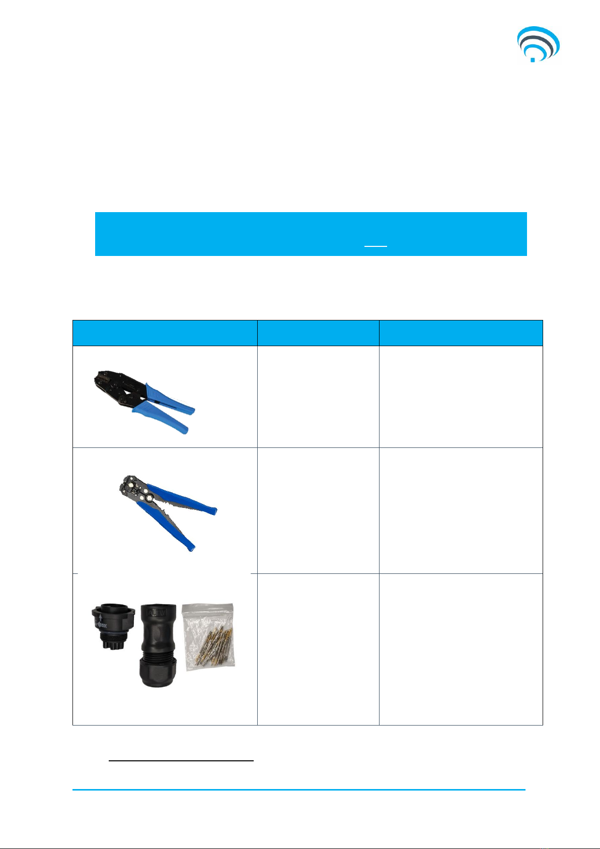
The following table details the required tools and components to successfully terminate
a cable to a Captis device.
TOOLS
DEFINITION
COMMENT
Amphenol Pin Crimping
Tool
This tool is required to securely crimp
the cable conductor to the amphenol
pins.
(Not included)
Cable Stripping Tool
The tool allows for efficient removal of
conductor insulation prior to
termination.
(Not included)
Amphenol Connector
Components
Included with the Captis product. 4
terminal connectors provided with the
Pulse 1.2 and Pulse Lite or 18
terminal connectors provided for Multi
1.2 and Recharge.
The amphenol pins1are suitable for
20-22AWG cable conductors
Table 1
1
The same Amphenol pins are provided with each Captis model.

Captis Cloud Configuration Guide Page | 3
2.2 Compatibility
It is important to ensure that the sensor being terminated is compatible with the
selected Captis device. Please find compatibility details below noting that all approved
sensors
2
may be connected and logged at once. However, any more than 2 x digital
inputs may adversely affect battery longevity.
DEVICE
SENSOR INPUTS
Pulse 1.2 and Pulse Lite 1.0
•2 x Digital Inputs
Multi 1.2 and Recharge 1.2
•2 x Digital Inputs
•1 x 4-20mA Analogue Input
•1 x 0-10VDC Analogue Input
•1 x Serial Input (Modbus RS232/RS485)
•1 x 1-Wire Input
Table 2
3 Terminating
When terminating cable into the Captis’Amphenol connector please follow these steps:
1. Prepare the cable
2. Crimp the pins
3. Secure the pins
4. Fasten the connector
3.1 Prepare the Cable
The following diagrams outline how to prepare the sensor cable for termination. These
guidelines support the manufacturers specification.
Table 3
Strip Insulation Length (A)
Strip Jack Length (B)
3.5mm –4mm
16mm –18mm
2
Please contact support@kallipr.com to ensure the selected sensor is compatible with the selected Captis device.

Captis Cloud Configuration Guide Page | 4
3.2 Crimp the pins
The following steps outline how to securely crimp the amphenol pin to the cable
conductor. Please note, only the crimping tool listed below is recommended for
crimping these pins. Failure to use the recommended tool may result in non-
compliant installations.
Table 4
3.2.1 Step 1
Insert the crimp contact into the opening of the crimp tool, with the crimp opening
facing the top of the tool.
3.2.2 Step 2
Insert the stripped cable into the crimp barrel.
Ensure that the cable conductor is in contact with the crimp tabs associated with
dimension B, and the cable insulation is in contact with crimp tabs associated with
dimension D, as seen in Figure 1 below:
Figure 1
3.2.3 Step 3
Squeeze the handle of the crimping tool together firmly until the tool releases.
3.2.4 Step 4
Visually inspect the crimp for proper termination. A light tug on each termination will
ensure the crimp is mechanically adequate.
TOOL
MANUFACTURER PART
NUMBER
Amphenol Crimping
tool
5A 20-22AWG
ASST-C-05-W-A

Captis Cloud Configuration Guide Page | 5
3.3 Secure the pins
Please ensure that care is taken to select the correct terminal for each pin as the
connector is not suitable for pin removal. As such, there is no recommended practice
for pin removal.
After all of the cable conductors have been successfully fastened to the crimps, the
amphenol pins may be inserted into the pin receptacles.
Insert each pin into each receptacle until you hear a small click.
Attempt to remove each pin with light force after this click to confirm they are securely
fastened.
If you do make an error, please call your distributor and request a replacement
connector kit and replace the connector assembly. It is recommended that spare
connector kits are carried by Captis installers to prevent multiple site visits in the event
of a mistake.
3.4 Fasten the Connector
Install the Clamp Ring to the housing-with-contacts by screwing. Make sure to apply
the correct tortional force.
Clamping ring torque: 6 ~ 8kgf.cm(0.58 ~ 0.78 Nm)
Figure 2
Ensure that the clamp seal aligns with the clamp ring surface, as seen below:
Figure 3

Captis Cloud Configuration Guide Page | 6
Finally, install the sealing nut to the clamp ring by screwing. Make sure to apply the
correct tortional force.
Clamping ring torque: 6 ~ 8kgf.cm(0.58 ~ 0.78 Nm)
Figure 4
4 Testing
Upon completion of the sensor termination, the connector may be secured to the Captis
receptacle.
Ensure that the Captis is correctly configured to receive the data from the connected
sensor.
If there is no data being transmitted by the sensor to the Captis device, please review
the terminations and sensor output.
Este manual sirve para los siguientes modelos
3
Tabla de contenidos
Manuales populares de Sistema de agua de otras marcas

Spirotech
Spirotech SPIROVENT SUPERIOR S250 Manual de usuario

Culligan
Culligan Aqua-Cleer Aqua-Cleer Advanced Drinking Water... Manual de usuario

A.O. Smith
A.O. Smith Dura-Max AJH - 1000A - P Manual de usuario

Microline
Microline T.F.C.-4 Manual

Eureka Forbes
Eureka Forbes Aquaguard Select Manual de usuario

Cetetherm
Cetetherm AquaEfficiency Manual de usuario


