K9JM CI-V Manual de usuario
K9JM CI-V Router User Guide
for software version 1.11
March 201
What can be supplied:
The K9JM CI-V Router is sold in two forms:
1. The CI-V interface board for the rduino Mega 2560, assembled and tested
2. Full K9JM CI-V router. ssembled and tested. Includes
CI-V interface board
rduino Mega 2560 Board
Modified rduino Case
Power Supply (9volt 1 mp)
USB male to USB male B, 6 feet
Note: International customers. The US Government requires an special export license to
ship internationally " dvanced Microprocessors". The paper work and cost to acquire this
license prohibits me from exporting "full systems".
The K9JM CI-V Router:
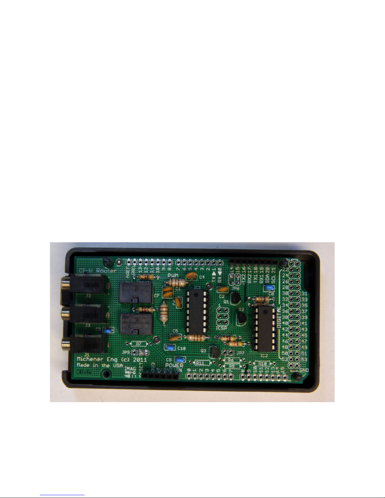
The K9JM CI-V router is an rduino stand alone computer, an Icom CI-V interface "shield" and
software. The CI-V rduino shield board is the board shown above. The software, both source
code and prebuilt, ready to load binary code is available on the K9JM.com website.
Page 1
Illustration 1: CI-V Router Shield for the Arduino Mega 2560

To make a complete CI-V router, the following elements are suggested. Many people may wish to
build this into their own enclosure and provide additional functionality. Below is the shopping list
that comes with the "everything" option. The "everything" option comes programmed, tested and
configured for CI-V at 9600 and the computer 38400 with "Transceive on. Read the CI-V router
configuration for details. The device will be ready to wire and operate.
Many hams have well stocked junk boxes. Some of these items may already be found.
For the "everything" CI-V Router includes the following items, assembled and tested.
Item 1: Arduino Mega 2 60 board
http://arduino.cc/en/Main/ rduinoBoardMega2560
Distributors for the rduino board are listed:
http://arduino.cc/en/Main/Buy
Prices and available vary.
http://www.nkcelectronics.com/arduino-mega-2560.html
Item 2: Arduino case: plastic case that can be easily modified to house the "stack" of the
rduino Mega board and the CI-V Router shield board.
http://www.mouser.com/ProductDetail/ rduino/ 000009/?qs=sG EpiMZZMs0PWRNvpRp0DTFs%2fiaewZY
http://www.amazon.com/ rduino-Box-for/dp/B003ZKJNVY/ref=sr_1_4?ie=UTF8&qid=1328474339&sr=8-4
ITEM 3: USB A male to B male cable – These cables are everywhere. They are available at
about any store that carries electronics in the world. If you're like me there are a dozen of them in
your cable box.
http://www.amazon.com/ mazonBasics--Male-B-Male-Cable-Meters/dp/B001TH7GU /ref=sr_1_5?ie=UTF8&qid=1328474923&sr=8-5
I would avoid the very cheap cables, but these have been know to work,
http://www.amazon.com/Black-Hi-Speed-Printer-Scanner-Lexmark/dp/B0030FP44Y/ref=sr_1_16?ie=UTF8&qid=1328474923&sr=8-16
ITEM 4: Wall power supply. OPTION L. The entire CI-V router can be powered off the USB,
or it can be powered off an external power supply. The external power supply is handy when the
router is in use when the computer is off. Note: If the CI-V router is powered down, a relay
connects all the CI-V bus together, so communications between units will still occur, without the
"protection" of the router. Must be capable of DC voltage between 7.0 and 10.0 volts at 150ma.
http://www.amazon.com/Wall- dapter-Power-Supply-650m /dp/B003XZSZWO/ref=sr_1_1?ie=UTF8&qid=1328474449&sr=8-1
ITEM : Male jumper. Used for putting the CI-V router into configuration mode. ny piece of
bare wire will work
Page 2

Wiring
Wiring is straight forward.
There is no difference between the three CI-V ports, so run a shield cable to each item.
Connect the USB cable, USB male to the computer and the USB B male rduino Board.
n optional wall mounted power supply can be connected to the CI-V router.
IMPORT NT: The router can be powered off the USB port, however when the computer is
off, the router will "bypass" and connect all the ports together. Things will still be
functional, but the router will be inactive. This is recommended ONLY when there are just
two devices connected to the CI-V port.
IMPORT NT: The router at first opportunity after reset builds a table of discovered
equipment on each port. IF you move anything from port to port of the CI-V router it is
advised to RESET the CI-V router. This is done by hitting the reset button, or turning the
router off by removing all power sources, including the USB.
Page 3

Getting started
There are six steps that are necessary to get the CI-V Router up and running:
1. Installing rduino USB Drivers (Windows only)
2. Downloading CI-V software to the rduino board
3. Configure the CI-V Router
4. Configure your ICOM Radios
5. Configure the PC Host Software
6. Configure (sync) the PW-1 mplifier (required if use with PW-1)
STEP ONE: Installing Arduino USB Driver and COM Port determination
Note: When in doubt re-boot. Whenever changing USB serial ports, it is my experience
that a Windows reboot is almost always required if **anything** is changed. Installed a
driver, change COM port number. When in doubt re-boot.
Obtain and install the rduino USB Drivers for the rduino Mega 2560. On the internet go to the
rduino software download site
http://arduino.cc/en/Main/Software
and obtain the lastest rduino released software. It must be version 1.0 or greater. The only thing
that will be required is the drivers, but you will have to download everything. If you wish to
modify the source code, you will need the full package. This site has helpful information that
details installation on installtion of drivers. Follow these instructions.
http://arduino.cc/en/Guide/Windows
I usually download the zip version. Then move (drag and drop) the arduino-1.X.X folder from the
zip file to your desk top. Where X.X is the current version number. Then when loading the driver
for the unknown device, point it
... Desktop/araudino-1.X.X/drivers and hit okay.
The rdunio board can be powered off the USB port, so no external power supply is required.
While installing the driver some versions of windows will warn you that the driver is not verified or
certified by Microsoft. This is normal, do not be alarmed, just acknowledge the "warning".
Page 4

Note: If you have a Rev3 board properly installed, on the above "Computer Management" screen
will read " rduino Mega 2560 R3 (COM#)"
If you are running Windows, and if the rduino is connected to the PC, it should be visible in your
computers "Computer Management" screen. Please note which COM port was assigned to rduino
Board. If this port is too high or if you wish to change the COM port assignment, right click on the
item (as shown above) and select "Properties" and click on the "Port Settings" tab and click on the
" dvanced..." button. The rest of the parameters are the defaults and are always over written by
the program.
Page 5
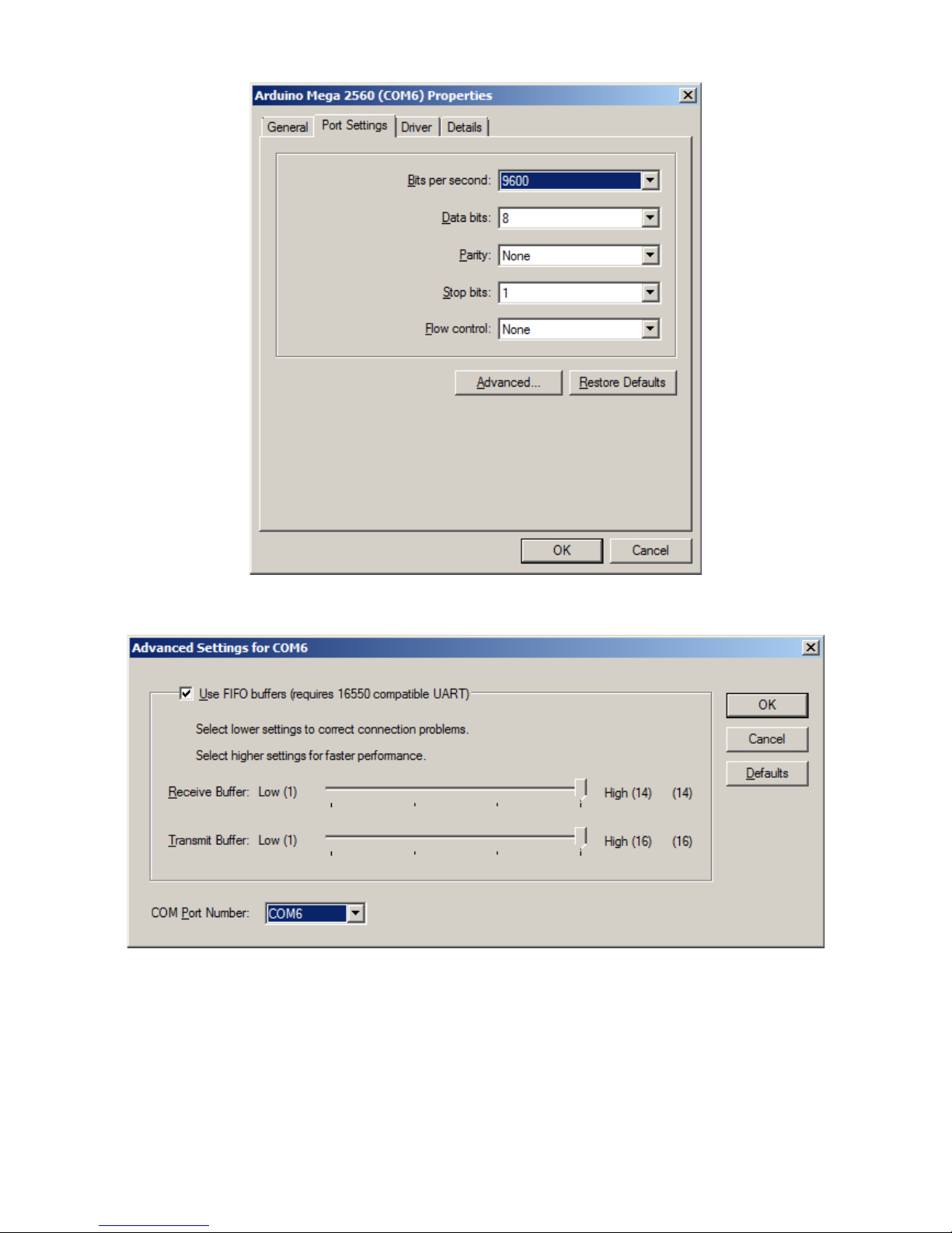
nd select the desired COM Port number in the highlighted box
If the port is marked "IN USE" and it is a "virtual" COM device that is currently not in the machine,
select it to take over that device. If you have a physical COM port that you wish to re-assign to
another number, thus freeing that COM port on your machine, select the device in the device
manager, right click on "Properties" and select the "Port Settting" tab.
Page 6

Now select the Change Port Number button. The rest of the parameters are the defaults and are
always over written by the program.
Using this technique one can organize the COM port number on the computer to hopefully make
sense and to work will all desired programs.
NOTE: REMEMBER THE COM PORT NUMBER SSIGNED TO THE RDUINO MEG 2560
BO RD
There are many YouTube.com videos that detail step by step how to install drivers for the rduino
that may be useful.
STEP TWO: Uploading CI-V Router software
If you have a complete unit, software was installed before shipping, skip this step. If you ever wish
to install the latest software, for any reason, follow this proceedure. To get the latest router software
go and download
http://www.k9jm.com/CIV_Router/download.html
On this page you will find release notes and dates so you can see what new features or bugs were
fixed since your software version.
Unzip the "prebuilt" file into a directory. In the directory there should be avrdude, avrdude.conf a
.hex file and a batch file upload.bat
Page 7

With the rduino connected to the computer and remembering the COM Port number from above,
open a Command Prompt window, navigate to this directory and run the following command
upload #
Where the # is the COM Port number for the rduino Mega board that you hopefully remembered
from the first step.
In about five seconds the task should be complete. Below is a "typical output". The name and the
size of the .hex file will be different, but eventually it should say the flash was verified and tell you
Thank you.
Note: When the software installs on a virgin rduino board, it will self configure to operate at
38000 baud for the computer and 9600 for the CI-V bus.
Typical output
C:\Users\James\DLTest>avrdude.exe -Cavrdude.conf -pm2560 -c iring -P\\.\COM9
-b115200 -D -U flash: :K9JMBasicRouter.hex:i
avrdude.exe: AVR device initialized and ready to accept instructions
Reading | ################################################## | 100% 0.04s
avrdude.exe: Device signature = 0x1e9801
avrdude.exe: reading input file "K9JMBasicRouter.hex"
avrdude.exe: riting flash (13500 bytes):
Writing | ################################################## | 100% 2.27s
avrdude.exe: 13500 bytes of flash ritten
avrdude.exe: verifying flash memory against K9JMBasicRouter.hex:
avrdude.exe: load data flash data from input file K9JMBasicRouter.hex:
avrdude.exe: input file K9JMBasicRouter.hex contains 13500 bytes
avrdude.exe: reading on-chip flash data:
Reading | ################################################## | 100% 1.79s
avrdude.exe: verifying ...
avrdude.exe: 13500 bytes of flash verified
avrdude.exe: safemode: Fuses OK
avrdude.exe done. Thank you.
C:\Users\James\DLTest>
lternatively, you can download the source files, place the library files in the library and open the
sketch and build the application. To learn how to do this read up on the rduino site.
If you do not wish to configure the router, re-attach the CI-V "shield" on the rduino board.
STEP THREE: Configuring the CI-V Router
NOTE: When touching the rduino and CI-V router electronics be sure to employ anti-static
proceedures.
Page 8
On a virgin rduino board or any completed system shipped, the configuration will be in the
default state. The baud rate for the CI-V ports is 9600 and 38400 for the USB 'computer'. To
confirm or change these parameters, the following proceedure can be followed.
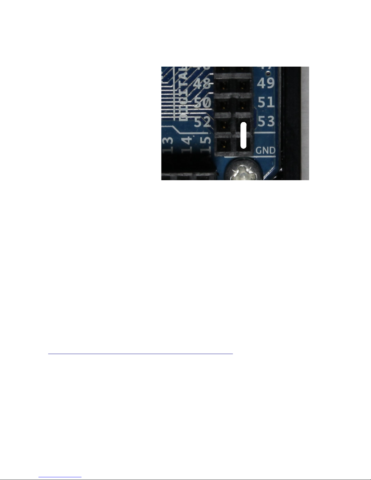
Configuring the CI-V Router is done by
restarting or resetting the rduino Mega
board with Pin 53 connected to ground.
t start time, it checks to see if pin 53 is
grounded. If it is, a small program is run
within the router where the user interacts
with a serial terminal program and it
permits the user to configures the
EEPROM that is internal to the tlmel
microprocessor. Parameters can be
changed at will at any time using this
method. What can be established is the
baud rates for the CI-V bus as well as the
baud rate for the computer interface, and
the "transceive" function. Described
later. To operate as a router, the board
must be restarted with pin 51 NOT
grounded, leaving it unconnected is fine.
The board may be restarted by removing
all power from the unit, including USB,
or by hitting the 'reset' button on the back center of the rduino Mega board.
Note: The full unit ships with a jumper assembly that is plugged between the two ground pins. To
jumper pin 53 to ground, simply unplug the jumper and rotate it 90 degrees, so that it shorts pin 53
to ground. When done, be sure to store the jumper in the same location as it was shipped.
Resetting or starting the rduino with pin 53 connected to ground will run the configuration
program. This program changes the content of an EEPROM and it saves the changes after each
entry has been made.
If you already have and know how to use your favorite serial terminal program, use it. If you do not
have a favorite serial terminal program, might I suggest PuTTY.
There is a version of PuTTY that runs on almost every operating system. It is free and very useful
and can be downloaded from:
http://www.chiark.greenend.org.uk/~sgtatham/putty/download.html
There are many options here, for windows it is best use the "Windows installer for everything
except PuTTYtel" option.
You will want to configure the serial program for a baud rate of 115200 8 bits 2 stop no parity no
flow control.
In PuTTY select the 'Serial' radio button, the COM port on 'Serial line' and 'Speed' is set to 115200
and hit 'Open'
Note: The Saved Session are saved session on my computer, once you have a
Page 9
Illu
stration 1: Jum er in 53 to ground

configuration you like, give it a name in the "Save Session" line and hit save.
NOTE: This configuration program LW YS runs at 115200 baud rate regardless of the
settings configured.
Pressing the reset button on the rduino will bring up the following:
Note: These settings do not represent the default setting as shipped. The first line will tell
you the version and date of the current CI-V router software. The second line tells the
amount of free static R M available for the program to use. The board has 8K bytes.
t this point the user can input either 1 through 13 followed by "ENTER".
Selecting either 1 or 2 brings up a second 'baud rate setting' menu, where the user can select the
desired baud rate. Or if 3 through 6 is selected the boolean can be toggeled between True and
False by selecting the parameter.
Transceive, default is true, is discussed later. It is best to leave at true for single radio operation.
USB Echo, default is true, and it causes any command sent from the computer to the USB port to be
echoed back. This is required for the program DX4WIN, and perhaps others. It does, slightly slow
down polling in other programs.
Subwitch, default is true, has the router running in a passive mode, where everything is routed.
Page 10
Tabla de contenidos
Manuales populares de Enrutador de red de otras marcas


NETGEAR
NETGEAR FS526T - Switch Manual de usuario

Korenix
Korenix JetNet 5710G Series Manual de usuario

Automated Logic
Automated Logic ZN551 Manual del propietario

Cisco
Cisco ASR 1000 Series Manual del operador

EnGenius
EnGenius ESR-9710 Manual de usuario

Cisco
Cisco 805 Series Instrucciones de funcionamiento y seguridad