JR SX600 Manual de usuario

6-CHANNEL COMPUTER RADIO


3
SX600 MANUAL • Table of Contents
QUICK START
4
I. INTRODUCTION
1. Using This Manual 6
2. Features 6
2.1 Transmitter Features 6
2.2 Receiver Features 6
2.3 Servo Features 7
2.4 Servo Layout 7
3. Specifications 8
3.1 System Specifications 8
3.2 Transmitter Specifications 8
3.3 Servo Specifications 8
3.4 Receiver Specifications 9
3.5 Charger Specifications 9
3.6 Airborne Battery Pack 9
4. Battery Charging 10
4.1 Transmitter/Receiver 10
4.2 Charger 10
5. Trainer System 11
II. SX600 MANUAL
1. Transmitter Controls 12
1.1 Control Identification and Location 12
1.2 Receiver Channel Assignment/
Transmitter Throttle ALT 12
1.3 Transmitter Rear 13
1.4 Control Stick Length Adjustment 13
1.5 Direct Servo Control (DSC) 14
1.6 Neck Strap Attachment 14
2. Connections 15
2.1 Installation Requirements 15
2.2 Connections 15
3. Key Input and Display 16
4. Battery Alarm and Display 16
5. Input Mode and Functions 17
5.1 Normal Display 17
5.2 Direct Trim Access Display 17
5.3 Mode Types 17
5.4 Throttle Cut 17
5.5 System Mode 18
5.6 Function Mode 18
6. Functions (System Mode) 19
6.1 Data Reset 19
6.2 Model Selection 20
6.3 Wing Type Selection 20
6.4 Model Name Entry 23
7. Functions (Function Mode) 24
7.1 Servo Reversing 24
7.2 Dual Rate 25
7.3 Sub Trim 26
7.4 Travel Adjustment 27
8. Data Sheets 28
III. IMPORTANT INFORMATION
1. General Notes 31
2. Daily Flight Checks 31
3. Warranty Coverage 32
4. Repair Service Instructions 32
5. Frequency Chart 33
6. Notes on the RS600 Receiver 35
TABLE OF CONTENTS
We strongly encourage all prospective and current
R/C aircraft pilots to join the Academy of Model
Aeronautics. The AMA is a non-profit organization
that provides services to model aircraft pilots. As an
AMA member you will receive a monthly magazine
entitled Model Aviation, as well as a liability
insurance plan to cover against possible accident
or injury. All AMA charter aircraft clubs require
individuals to hold a current AMA membership
prior to operation of their models. For further
information you can contact the AMA at:
Academy of Model Aeronautics
5151 East Memorial Drive
Muncie, IN 47302
(317) 287-1256
Thank you for purchasing the JR SX600 6-Channel
Radio System. This unit has been designed to
provide the modeler with a high-quality, user-
friendly radio system that can be depended upon
for years to come.
It’s important that you carefully read this manual
before attempting to operate your system. Please
pay particular attention to Page 10, Introduction 4,
“Battery Charging.”
AMA INFORMATION
INTRODUCTION TO THE SX600 RADIO SYSTEM
4SX600 MANUAL Quick Start
SX600 QUICK START
In this manual you will find in-depth instructions
that detail all the steps and procedures you should
follow in order to program each of the SX600’s
features. For modelers who want to get into the
air fast, we have provided Quick Start. Quick
Start covers the basic programming information
necessary to get you airborne. Later, when you want
to learn more about specific features of the SX600,
turn to the appropriate pages(s) in this manual for
more detailed programming information.
Note: Please charge the system batteries as
indicated in step 4.1 before attempting the
Quick Start setup and again before flying the
model.
Turn on the transmitter and check to ensure
that the aileron, elevator, and rudder trim
valves are set to the 0 (neutral) position.
Next, set the throttle trim valve to the full low
(-40) position by pressing the throttle trim
lever down.
DIGITAL TRIM SETTINGS
1
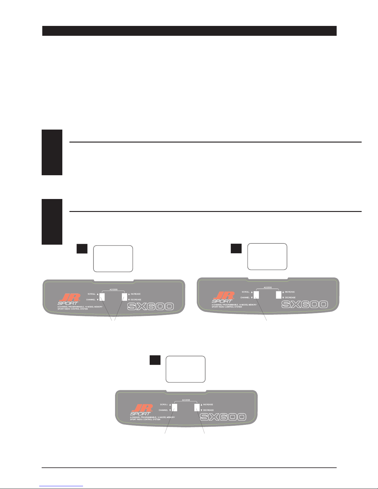
SERVO REVERSING
2
With the transmitter on, press the Scroll and Increase buttons
upward simultaneously until a beep is heard.
Press the Scroll button (if necessary) until
“REVERSE-NORM” appears on the screen.
AB
Press the Channel button to select the
channel you want to reverse.
Press the Increase or Decrease button to
reverse the direction of the
channel you selected.
C
THR
—
THR
—
THR
—

5
SX600 MANUAL Quick Start
SX600 QUICK START
Press the Scroll
button until
“TRV ADJ” appears
on the screen.
Press the Channel button to
select the channel on which
you want the travel adjusted.
INCREASE
To increase the travel, move
the stick (i.e. aileron) to the
right then press the Increase
button to adjust the right
travel. Release the Increase
button and move the same
stick to
the left. Press the Increase
button to adjust the left travel.
DECREASE
To decrease the travel, move
the stick (i.e. aileron) to the
right then press the Decrease
button to adjust the right
travel. Release the Decrease
button and move the same
stick to the left. Press the
Decrease button to adjust the
left travel.
AB
C
TRAVEL ADJUSTMENT
3
Press the Scroll and Increase buttons upwards
simultaneously to return to the main screen and exit the
Function mode.
Note: Before flying, check that the direction and travel of all control
surfaces move correctly.
Before the initial start of your model, please
check to ensure that when the Throttle Cut
button is pressed, the engine’s carburetor
barrel will move to the fully closed (engine off)
position.
This safety feature ensures that the engine can
be shut off immediately in case of a problem or
safety concern.
THROTTLE AUTO CUT
4
AIL
+100%
AIL
+107%
A C i
10.4v

6SX600 MANUAL • INTRODUCTION 1: Using This Manual / INTRODUCTION 2: Features
The SX600 is a full feature introductory
computer radio that can be used for airplanes.
A blank data sheet is included at the end
of this manual. Once you have input all the
necessary data into your transmitter for a
particular model, we strongly recommend that
you write that information down on a copy of
the data sheet provided. This is to ensure that,
in the rare case of a memory failure, you will
not lose your data.
INTRODUCTION 1: USING THIS MANUAL
USING THIS MANUAL
1
• Easy-to-read LCD screen
• 10-model memory
• Trainer system compatible with most other
JR FM radios
• 2 conveniently mounted direct-access
programming levers
• Computer designed ergonomically
styled case
• Adjustable stick length
• Dual rates for aileron and elevator
• Digital trims with Direct Access feature
• Throttle trim only affects idle position
• Two-speed scrolling—press and hold the
appropriate button to scroll quickly or press
and release to scroll in steps
• Flaperons mixing
• Delta wing mixing
• V-tail mixing
• Throttle cut safety feature
RS600 Slimline Receiver
• The RS600’s extremely compact “slimline”
design allows it to fit easily in limited
spaces.
• An independent laboratory ranked the
RS600 receiver with JR’s patented ABC&W
circuitry as one of the best receivers ever
tested in terms of 3IM, 2IM, adjacent
channel rejection, signal-to-noise ratio, and
on-channel capture point.
• A special “unwanted interference limiter”
ignores signals outside of the RS600’s
band width when the receiver is on and
the transmitter is off. The limiter also
prevents servos from random glitching when
other transmitters are operating in close
proximity.
• The electrical circuitry in the RS600 is state-
of-the-art surface mount technology (SMT).
These SMT components draw less current,
thus increasing flying time. Flush mounting
of these components also reduces the risk
of vibration, wear, and damage.
• The RS600 is compatible with all JR FM-
transmitting radios.
TRANSMITTER FEATURES
2.1
RECEIVER FEATURES
2.2
INTRODUCTION 2: FEATURES

7
SX600 MANUAL • INTRODUCTION 2: Features
INTRODUCTION 2: FEATURES CONTINUED
ST47 Servo
• An ultra-tight deadband amplifier ensures
accurate neutral centering
• Low current drain
• An indirect drive feedback potentiometer
gives additional protection from vibration
SERVO FEATURES
2.3
SERVO LAYOUT
2.4
Servo Eyelet
Servo Mounting Flange
Rubber Grommets
Top View
Rubber Grommets
Servo Case
Servo Lead w/Connector
Servo Output Shaft
Servo Mounting Flange
Servo Arm/Horn
Servo Arm Retaining Screw

8SX600 MANUAL • INTRODUCTION 3: Specifications
INTRODUCTION 3: SPECIFICATIONS
SYSTEM SPECIFICATIONS
TRANSMITTER SPECIFICATIONS
3.1
3.2
SYSTEM NAME SX600
TRANSMITTER BODY SX600
RECEIVER RS600
CHARGER NEC-221
AIRBORNE BATTERY JSPB700
SERVOS NES-ST47 x 4
ACCESSORIES Mini Switch
12" Aileron Extension
Servo Accessories
Instruction Manual
TYPE AIRPLANE
MODEL NUMBER SX600
ENCODER 6-CHANNEL COMPUTER SYSTEM
RF 72 MHZ
MODULATION PPM (FM)
OUTPUT POWER APPROXIMATELY 1 WATT
CURRENT DRAIN 200MA
POWER SOURCE 1.2V X 8 NICAD (9.6V) 600MAH
OUTPUT PULSE 1000-2000 (1500 NEUTRAL)
TYPE AIRPLANE
SERVO SPECIFICATIONS
3.3
TORQUE (OZ/IN) 47
SPEED (SEC/60°) .24
WEIGHT (OZ) 1.55
SIZE (IN) (W X L X H) 0.73 X 1.52 X 1.32
BB NO
MOTOR 3-POLE FERITE
TYPE ST47

9
SX600 MANUAL • INTRODUCTION 3: Specifications
RECEIVER SPECIFICATIONS
3.4
CHARGER SPECIFICATIONS
AIRBORNE BATTERY PACK
3.5
3.6
MODEL NUMBER RS600
TYPE 6-CH/FM SLIMLINE W/ABC CIRCUITRY
FREQUENCY 72MHZ
SENSITIVITY (MICROSECONDS) 5µS MINIMUM
SELECTIVITY 8KHZ/50DB
WEIGHT (OZ) .64 OZ
SIZE (IN) (W X L X H) 1.84 X 0.98 X 0.61
RECEIVER ANTENNA 39" FOR ALL AIRCRAFT FREQUENCIES
TYPE RS600 FM
MODEL NUMBER NEC-221
INPUT VOLTAGE AC 100-120V
OUTPUT CURRENT 50MAH TX/50MAH RX
CHARGING TIME 15 HOURS
TYPE AIRPLANE
MODEL NUMBER JSPB700
VOLTAGE 4.8V
SIZE (IN) (W X L X H) 2.24 X 0.59 X 2.05
WEIGHT (OZ) 3.3
TYPE AIRPLANE
INTRODUCTION 3: SPECIFICATIONS CONTINUED

10 SX600 MANUAL • INTRODUCTION 4: Battery Charging
INTRODUCTION 4: BATTERY CHARGING
The pilot lamps should always be on during the
charging operation. If they are not, make sure
you have turned off both the transmitter and
receiver.
Do not use the charger for equipment other
than JR. The charging plug polarity may not be
the same, and equipment damage may result.
Do not use other manufacturers’ after-market
accessories that plug into the transmitter’s
charging jack. If you do, any damage that
results will not be covered by warranty. If you
are unsure of compatibilities with your radio,
seek expert advice before doing anything to
avoid possible damage.
During the charging operation, the charger’s
temperature is slightly elevated. This is normal.
CHARGER
4.2
It is imperative that you fully charge both the
transmitter and the receiver battery packs prior
to each day of flying. For the initial charge,
leave the charger and batteries hooked up
for 20-24 hours in order to fully charge both
battery packs to peak capacity. For subsequent
charges, leave the charger and batteries hooked
up overnight (approximately
16 hours).
The charger supplied with this system is
designed to recharge your transmitter battery
at a rate of 50mA. The receiver battery pack will
charge at 50mA for the 700mAh battery pack.
TRANSMITTER / RECEIVER
4.1
Transmitter Only
The center pin on all JR remote control systems
is negative. Therefore, the center pin on all JR
chargers is negative, not positive. This is different
from any other manufacturers’ chargers and radio
systems. Beware of improper connections based
on “color code” wire leads as they do not apply
in this instance. You must make certain that
the center pin of your JR transmitter is always
connected to the negative voltage for correct
polarity hookup.
RED–POSITIVE / BROWN–NEGATIVE
ORANGE–SIGNAL
BLACK WIRE WITH WHITE LINE
TO NEGATIVE
BLACK TO POSITIVE
CHARGER PIGTAIL FOR RECEIVER
CHARGER PIGTAIL FOR TRANSMITTER
CENTER
PIN IS
NEGATIVE
RIGHT SIDE OF TRANSMITTER
OUTSIDE IS POSITIVE
Tabla de contenidos
Otros manuales de Mando a distancia de JR

JR
JR XF421EX Manual de usuario

JR
JR PCM9X II Manual de usuario

JR
JR JR DSM 12x Instrucciones de funcionamiento

JR
JR 10X HELICOPTER VERSION Manual de usuario

JR
JR XF631 Manual de usuario

JR
JR XP6102 Manual de usuario

JR
JR python Manual de usuario

JR
JR X9303 2.4 Manual del propietario

JR
JR XP652 Manual de usuario

JR
JR XP9303 Manual de usuario


