
Johansson 6506 Manual de usuario

1
User Manual
- Designed for both digital and analogue channels,
- 2 UHF input / 1 output,
- 8 programmable clusters,
- UHF channels 21 to 60, 4G/LTE protected.
- Each cluster can have 1 to 7 channels bandwidth,
- Easy programming by using one rotary / push button viewed on 2 digits display and LEDs
for each cluster,
- Accurate equalization of levels using 1 dB step attenuators,
- Switchable 20 dB input amplifier to attenuate high input signals,
- Selectable DC power-pass on each input.
- Ref. 6506UK is supplied with UK type power adapter.
6506
6506UK
Multi Channel Programmable Filter-Equalizer
FEATURES
2
S
AFETY INSTRUCTIONS
Read carefully these instructions before connecting the unit.
The operating voltage is indicated on the adapter.
To prevent fire, short circuit, shock hazard:
Do not expose the unit to rain or moisture.
Install the unit in a dry location without infiltration or condensation of water.
Do not expose it to dripping or splashing.
Do not place objects filled with liquids, such as vases, on the apparatus.
If any liquid should accidentally fall into the cabinet, disconnect the power plug.
Refer to qualified technician before its further operation.
To avoid any risk of overheating:
Install the unit in a well aery location and keep a minimum distance of 15 cm around the
apparatus for sufficient ventilation.
Do not place any items such as newspapers, table-cloths, curtains ... on the unit that might
cover the ventilation holes.
The unit must not be exposed to any source of heat (sun, heater,..).
Do not place any naked flame sources, such as lighted candles, on the apparatus.
Do not install the product in a dusty place.
Pull out power plug to make the different connections of cables.
To avoid electrical shock, do not open the housing of adapter.
Cleaning :
Only use a dry soft cloth to clean the cabinet. Do not use solvent.
Servicing :
For repairing and servicing refer to qualified personnel.
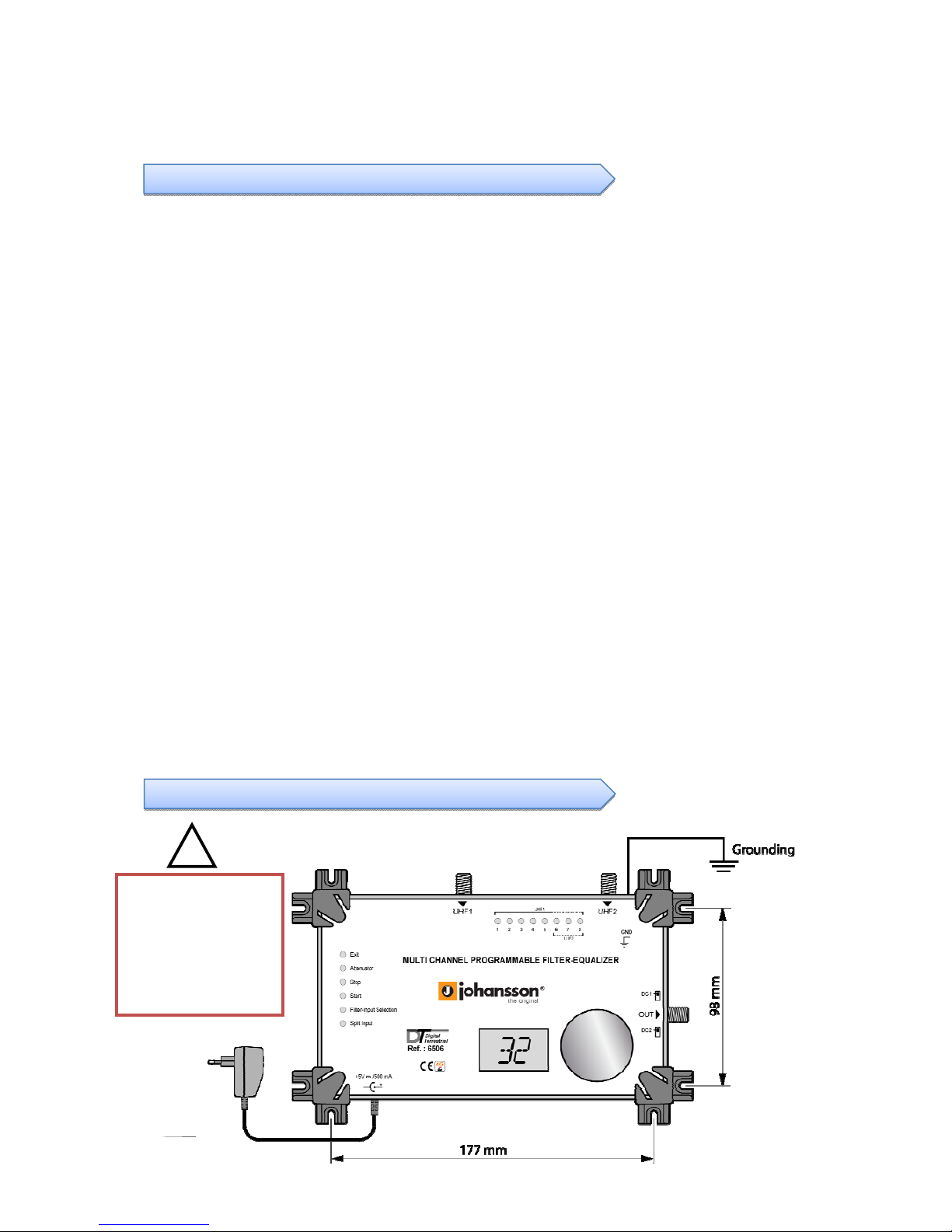
MOUNTING
WARNING!
Use only supplied
power supply.
A different voltage
and/or wrong polarity
destroys the
equalizer beyond
re
p
air!
!

3
DESCRIPTION

4
All parameters are set with the rotary button.
Each function and parameters are shown on 2 digits display and different LEDs.
Programming
OPERATION
Enter programming mode
- Make all the necessary connections and connect the equalizer to the mains.
The software version is displayed
followed by a dot.
- Push on the rotary button for more than 3 seconds to enter into programming
mode.
‐Turn the button to select the desired mode.
‐Push the rotary button to enter the selected mode.
The LED is now RED colored
‐Inside the mode, turn the button to select the parameter (input, cluster, level,…)
Display
‐Push the button to confirm the parameter setting.
LED returns to a GREEN color.
Repeatthisselectiontosetallparameters.

5
Note : the equalizer will go in ‘stand-by’ and will display a dot after 1 minute if the rotary /
push button is not activated.
Setting clusters / UHF Input
The equalizer has 2 UHF inputs which are splitted over 8 clusters.
There are three possible configurations :
Input UHF 1 UHF 2
Number of
Cluster (s) 8 0
7 1
5 3
Exit programming mode
- Turn the button to select Exit mode.
The LED is green.
- Push the button to confirm.
A dot is displayed.
CLUSTER PROGRAMMING
UHF 1 clusters are indicated by the RED LEDs
n°. 1, 2, 3, 4, 5, 6, 7 and 8.
UHF 2 clusters are indicated by the GREEN LEDs n° 6, 7 and 8
To set the number of cluster(s) per input:
-TurnthebuttontoselectSplitInputmode.
TheLEDisgreen.
-Pushthebuttontoconfirm.
TheLEDisred.

6
Setting channel / cluster
Each cluster has a bandwidth which can be programmed from 1 to 7 channels:
To set channel (s) per cluster :
In the next example cluster 1 is set for channel 22 to channel 26
TurnthebuttontoselecttheFilter‐InputSelectionmode.
‐Pushtherotarybuttontoentertheselectedmode.
TheLEDisnowREDcolored.
‐Insidethemode,turnthebuttontoselecttheclustertobeset.

7
‐Pushthebuttontoconfirm.
TheLEDisgreen.
TurnthebuttontoselecttheStartmode.
TheLEDisgreen.
‐Pushtherotarybuttontoentertheselectedmode.
TheLEDisnowREDcolored.
‐Turnthebuttontoselectthestartchannel.
Display
‐Pushthebuttontoconfirm.
TheLEDisgreen.
TurnthebuttontoselecttheStopmode.
TheLEDisgreen.

8
‐Pushthebuttontoentertheselectedmode.
TheLEDisredcolored.
‐Turnthebuttontoselectthestopchannel.
Display
‐Pushthebuttontoconfirm.
TheLEDisgreen.
Repeatthedashedframesonpage6,7and8tosetallparameters.
Notes:
‐Singlechannelmode:
WhentheStartChannelisselected,theStopChannelisautomaticallysetatthesame
value.
‐Parkfunction:toswitchoffthecluster,selectStartChannelandsetto“00”.
TheStopChannelgoesautomaticallyto00.

9
To check the channel settings of each cluster:
Ifthereareoverlappingclusters,thedisplaydotswillblinkalternately.
TurnthebuttontoselectFilter‐InputSelectionmode.
TheLEDisgreen.
‐Pushtherotarybuttontoentertheselectedmode.
TheLEDisnowREDcolored.
‐Turnthebuttontochoosetheclustertobechecked.
‐Thedisplayshowsthechannelswhichhavebeenset.
Examples:
Clusterisparked.
Clusterissettochannel22.
Blinking22and26:
Clusterissetfrom22to26.

10
Level setting
To set the level.
Example: setting the level of cluster 2
‐Pushthebuttontoexit.
TheLEDisgreen.
LEVEL ADJUSTMEN
T
TurnthebuttontoselecttheFilter‐InputSelectionmode.
The LED is green.
‐Pushtherotarybuttontoentertheselectedmode.
TheLEDisnowREDcolored.
‐Turnthebuttontoselectcluster2.
LEDisactivated
‐Pushthebuttontoconfirm.
The LED is green.
Este manual sirve para los siguientes modelos
1
Tabla de contenidos
Otros manuales de Ecualizador estéreo de Johansson


