JETI model Central Box Manual de usuario

EN
®
User Manual
EN

EN
1. Introduction ..................................................................................... 3 EN
1.1 Attributes ................................................................................... 4 EN
1.1.1 Central Box 100 ............................................................... 4 EN
1.1.2 Central Box 210/220 ...................................................... 4 EN
2. Description ........................................................................................ 5 EN
2.1 Central Box 210/220 ................................................................ 5 EN
2.1.1 Central Box 210 ............................................................... 5EN
2.1.2 Central Box 220 ............................................................... 6EN
2.2. Central Box 100 ....................................................................... 8 EN
2.3 Magnetic switch ( Central Box 210/220 ) ............................ 9 EN
3. Connection ..................................................................................... 10 EN
3.1 Power supply of Central Box 210/220 ................................ 10 EN
3.2 Power supply of Central Box 100 ......................................... 12 EN
3.3 Overload protection of servos ............................................ 14 EN
3.4 Connecting Central Box – EX Bus ........................................ 15 EN
3.4.1 Central Box 210/220 .................................................... 15EN
3.4.2 Connecting Central Box 100 ....................................... 15EN
3.5 Alternative functions – digital input .................................. 17 EN
3.6 Alternative functions - digital output ............................... 18 EN
3.7 OUT/IN pin (Central Box 100) .............................................. 19 EN
4. Configuration via JETIBOX ....................................................... 21 EN
4.1 Actual values .......................................................................... 22 EN
1 EN

EN
4.2 Minimum / Maximum values ............................................. 22 EN
4.3 Setting ..................................................................................... 23EN
4.4 Out Pin Set ............................................................................... 25 EN
4.5 Alarms .................................................................................... 26 EN
4.6 Service information .............................................................. 27 EN
5. Configuration via the DC/DS transmitter ............................. 28 EN
5.1 Settings .................................................................................... 29 EN
5.2 Alternate functions of pins .................................................. 30 EN
5.3 Servo Fail-Safe ....................................................................... 31 EN
5.4 Servo Output Mapping ....................................................... 32 EN
5.5 Telemetry ............................................................................... 33 EN
5.6 Telemetry Min/Max .............................................................. 33 EN
5.7 Reset to factory settings ...................................................... 34 EN
6. Firmware update ........................................................................... 35 EN
7. Safety precautions for working with magnets ................... 36 EN
8. Technical specifications of the Central Box .......................... 37 EN
9. Warranty, service and the technical support ....................... 38 EN
2 EN

EN
1 Introduction ENGLISH
The Central Box is a switchboard designed for the complete
management of servos in a model with an emphasis on safety. The
Central Box 100 and 220 have a unique design that provides
overload protection at each servo output. The Central Box 210
offers maximal unreduced power for each servo (servo outputs do
not have overload protection). The Central Box can manage up to
two batteries and fully supports the JETI EX telemetry system. Up to
three receivers with serial (PPM, EX Bus, S.BUS) output can be
connected to the Central Box 210 and 220. With JETI DC/DS
transmitter, the full potential of the Central Box can be used, such as
an easy way to configure the Central Box, EX telemetry, and very fast
servo response.
3 EN

EN
1.1 Attributes
1.1.1 Central Box 100
• Overload protection on each channel
• Possibility to connect up to 2 receivers with serial interface
PPM, EX Bus)
• Built-in Expander function
• 1x MPX battery input connector
• 100Hz mode of servo outputs (10ms period)
• Supports EX telemetry (voltage, current, capacity, and
temperature measurement, overload indication, ...)
• Easy settings changes via DC/DS transmitter
• Firmware updates by user
• Suitable for use with high voltage (HV) servos
• Compact size for easy installation
• Each output is individually configurable (channel assignment,
trim, reverse, ATV)
1.1.2 Central Box 210/220
• Central Box 210 has unreduced power for each servo (without
fuses)
• Central Box 220 has overload protection on each channel (4
outputs for high-torque servos and 11 outputs for standard
servos)
• Support of DITEX telemetry servos
• Possibility to connect up to 3 receivers with serial interface to
(PPM, EX Bus, S.BUS)
• Built-in Expander function for up to 3 sensors
• Input for magnetic switch or RC switch
• 2x MPX battery input connectors
• 100Hz mode of servo outputs (10ms period)
• Supports EX telemetry (voltage, current, capacity,
temperature measurement, …)
4 EN

EN
• Easy settings changes via DC/DS transmitter
• Firmware updates by user
• Suitable for use with high voltage (HV) servos
• Compact size for easy installation
• Each output is individually configurable (channel assignment,
trim, reverse, ATV)
2 Description
2.1.1 Central Box 210
• Central Box 210 has 15 outputs for servos (support of DITEX
telemetry servos).
• Each of the outputs can be operated in these modes:
- servo output (default setting)
- Digital output
- Digital input
- Ditex
• Moreover, channels E3/14 and E2/15 are also configurable to
alternative uses, such as:
- an input for telemetry sensor
- EX Bus expander – used for connecting devices which
support the EX Bus protocol (the Central Box, a sensor,…)
- S.BUS Output (only channel E2/15)
• E1/R3 port can be configured for use as:
- an output to connect a JETIBOX or Duplex EX receiver to
configure the Central Box
- an input for telemetry sensors
- EX Bus expander - used for connecting devices which
support the EX Bus protocol (the Central Box, a sensor,…)
- an input for receiver (supports only EX Bus protocol)
The E1/R3 slot is also used for the firmware update connection
(using the USBa - USB adapter).
2.1 Central Box 210/220
5 EN

EN
• R1 - primary input for connecting receivers with serial output
(EX bus, PPM or S.BUS)
• R2 - secondary input for connecting receivers with serial output
(EX bus, PPM or S.BUS)
• SW - input is reserved for connecting a magnetic switch or RC
switch (optional accessories).
• BATT1 and BATT2 – MPX connectors for connecting batteries or
a BEC, etc., to power the servos and receivers connected to
the Central Box.
2.1.2 Central Box 220
• Central Box 220 has 15 outputs for servos (support of DITEX
telemetry servos) with individual overload protection. Each of the
outputs can be operated in these modes:
- servo output (default setting)
- Digital output
- Digital input
- Ditex
• Channels 1, 2, 9 and 10 have protection for high-torque servo
up to 60 Kg.cm.
• Channels 3 - 8 and 11 - 15 have protection for standard servo
up to 30 Kg.cm.
• Channels E3/14 and E2/15 are also configurable to alternative
uses, such as:
- an input for telemetry sensor
- EX Bus expander – used for connecting devices which
support the EX Bus protocol (the Central Box, a sensor,…)
- S.BUS Output (only channel E2/15)
• E1/R3 port can be configured for use as:
- an output to connect a JETIBOX or Duplex EX receiver to
configure the Central Box
- an input for telemetry sensors
- EX Bus expander - used for connecting devices which
support the EX Bus protocol (the Central Box, a sensor,…)
- an input for receiver (supports only EX Bus protocol)
6 EN

EN
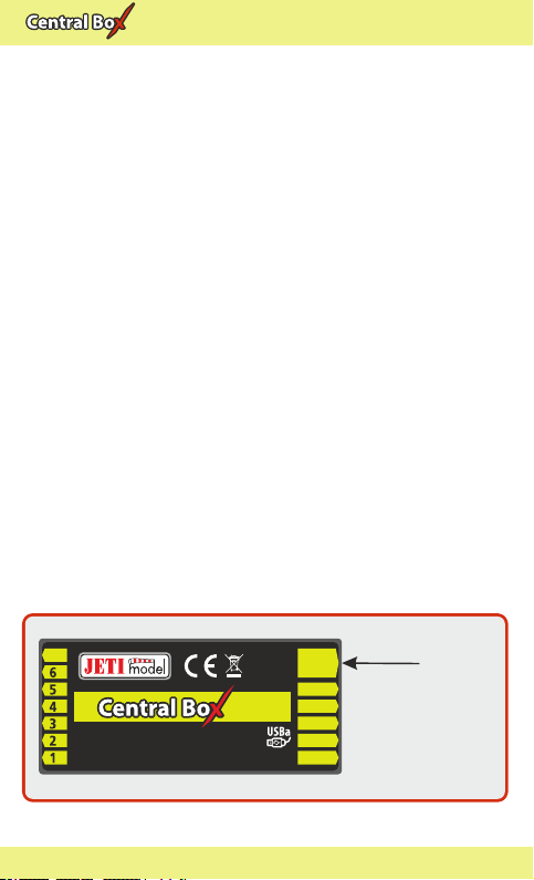
Fig. 1: Central Box210/220 description
E1/
E2
R1
R2
E3
R3
220220220
15 channel protected servo interface
RC Switch
Magnetic Switch
• The E1/R3 slot is also used for the firmware update connection
(using the USBa - USB adapter).
• R1 - primary input for connecting receivers with serial output
(EX bus, PPM or S.BUS)
• R2 - secondary input for connecting receivers with serial output
(EX bus, PPM or S.BUS)
• SW - input is reserved for connecting a magnetic switch or RC
switch (optional accessories).
• BATT1 and BATT2 – MPX connectors for connecting batteries
or a BEC, etc., to power the servos and receivers connected to the
Central Box.
7 EN
EN
2.2 Central Box 100
The Central Box 100 has 8 servo outputs with individual
overload protection , labeled with numbers for the output. Each
of the outputs can be operated in these modes:
servo output •
• digital input
digital output •
OUT/IN– universal input/output for switching additional
functions or for supervising the operational status.
Ext1 port can be configured for use as:
• an output to connect a JETIBOX or Duplex EX receiver to
either configure the Central Box or for the output of
telemetry data
• an input for telemetry sensors
• Ext1 slot is also used for the firmware update connection
• EX Bus expander - used for connecting devices which
support the EX Bus protocol (the Central Box, a sensor,…)
Rx1– primary input for connecting receivers with serial output
(Ex Bus or PPM)
Rx2– secondary (backup) input for connecting receivers with
serial output (Ex Bus or PPM)
BATT1– an input for batteries or a BEC, etc., to power the servos
and receivers connected to the Central Box
7
Rx 1
Rx 2
Ext.
Out/In
BATT
8
8 channel servo interface
100100100
input
voltage
4-14V
Input
Voltage
Fig. 2: Central Box 100 description
8 EN

EN
2.3 Magnetic switch ( Central Box 210/220)
The magnetic switch is used to turn the CB 210/220 ON or OFF . The
magnetic switch is connected to Central Box 210/220 by the
interconnection cable from normal Master port on the magnetic
switch to a slot labeled "SW" on the Central Box 210/220. To turn on
the Central Box using the magnetic switch it is necessary to hold the
supplied magnet carrier (key) to the target so that the carrier (key)
and the target on the magnetic switch are properly oriented
(align the dots).
Green LED
- flashing LED signals proper detection of the magnet key
- steady LED signals “ON” state
When the magnet key is held to the target in the proper orientation,
the green LED glow steadily after 1 second indicating that the
electronic switch is turned “ON”.
Switching „OFF” is done in a similar manner, when the magnet key
is held to the target in the proper orientation, after 1 second, the
green LED goes off and the system switches off.
If the switch is not plugged in the Central Box, the Central Box is
switched “ON”.
The system remembers whether it has been switched “ON” or „OFF”.
If the system is switched “ON” via the magnetic switch and then the
power supply is disconnected, when the batteries are re-connected
to the system automatically returns to the “ON” state. For safety
Fig. 3: Description of magnetic switch and the key
Key
Target
Led On
9 EN
Tabla de contenidos
Manuales populares de Unidad de control de otras marcas

Festo
Festo Compact Performance CP-FB6-E Manual de lista de piezas

Elo TouchSystems
Elo TouchSystems DMS-SA19P-EXTME Manual de usuario

JS Automation
JS Automation MPC3034A Manual de usuario

JAUDT
JAUDT SW GII 6406 Series Guía rápida

Spektrum
Spektrum Air Module System Manual de usuario

BOC Edwards
BOC Edwards Q Series Manual de usuario


