3.1 Installation Procedure –Cont.
Check the contents supplied against your packing list & DAS design.
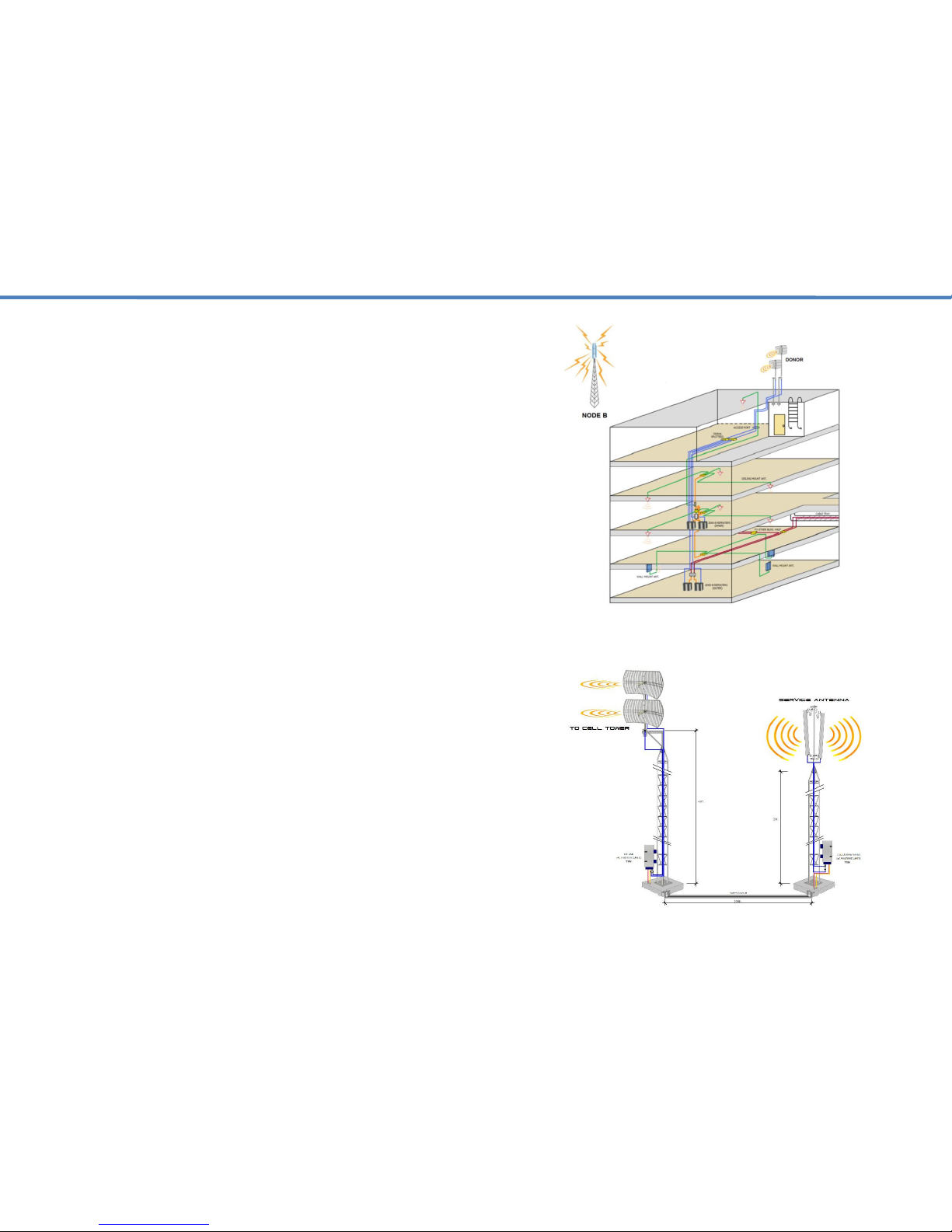
Identify a suitable location where the donor antenna will be installed on
the roof or at an elevated location free of any other antennas or
immediate obstructions. Confirm this location has the best input signal
for the carriers you would like to support using test equipment. Ensure
the location is properly isolated from any of the indoor service antennas
so as to avoid signal oscillation.
Identify the location for the head-end equipment and that suitable AC
power and a lightning ground is available. Using the DAS design
provided, walk the entire space to confirm all the components and cable
access paths of the DAS can be installed without any omissions.
Install the donor antennas at the suitable location identified and start the
cabling process. DO NOT COIL UP any excess coax you may have or
create any service loops. These are detrimental to cellular performance.
Be sure to weather proof all your external connections and fire stop all
ports of entry.
Carefully follow your DAS diagram to ensure all the components are
installed according to the design. Any alterations made to the system
layout without informing the DAS design engineer could result in system
performance failure or interference to the macro.
It’s EXTREMELY IMPORTANT that all your cable terminations be done
properly and line sweeps completed using the appropriate test
equipment. (Frequency Return Loss) Directional couplers MUST be
installed in the right direction and with the correct values as outlined in
the DAS design. DOUBLE-CHECK ALL YOUR WORK! The extra time
you invest to do so will pay-off with a smooth and successful
commissioning process.
If multiple repeaters are deployed, start by commissioning one repeater
at a time. It’s best to start with the frequencies that support voice
communication, then move on to data (4G, 5G, LTE). Upon
commissioning, quickly work towards getting the LEDs on the repeater
to a green status by adding attenuation as needed. First on the DL,
then on the UL.
If signal oscillation or a strong input signal is between 1~4dB over the
acceptable range then the Alarm LED for the respective band will turn
amber (See manual gain adjustment). If the signal oscillation is between
10-15dB then the Alarm LED for the respective band will turn red and
the circuit will then go into MUTE / Shutdown. This is as a result of not
having enough isolation between the donor and service antennas or the
input signal at the donor antenna is too strong.
3.2 Installation Procedure –Antenna Mounting.
In this case attenuate the DL gain on the repeater till the alarm LED
goes green and then match the UL gain to the same gain value.
Do not install the donor antenna near high voltage power lines.
Please take the necessary safety measures when working on heights.
Do not mount near or in the path of other antennas or satellite dishes.
It is recommended that you mount your donor antenna in a spot that is
free of any immediate obstructions. Making use of a dedicated mast or
mounting bracket is recommended for optimum antenna performance.