J.P. Instruments EDM-900 Manual de usuario

FAA Approved Installation Manual for the Report No 908
EDM-900 and EDM-930 Page 1 of 56 Rev I
Primary Engine Data Management System Date 1-18-2013
TABLE OF CONTENTS
1. Revisions ______________________________________________________________________________________ 2
2. Read This First _________________________________________________________________________________ 2
3. Instrument Labeling______________________________________________________________________________ 3
4. Operation and Abbreviations ______________________________________________________________________ 4
5. Locating and Installing the Indicator and Remote Alarm Display (RAD and Alert Light) ________________________ 8
6. EDM-900/930 Key information installation __________________________________________________________ 10
7. Routing the Wiring Harnesses_____________________________________________________________________ 11
8. Power Connection ______________________________________________________________________________ 11
9. Probe Wiring __________________________________________________________________________________ 12
10. Wiring Markings _______________________________________________________________________________ 12
11. Exhaust Gas Temperature Probe (EGT) Installation ___________________________________________________ 12
12. RADIAL Engine EGT_____________________________________________________________________________ 13
13. Turbine Inlet Temperature (TIT) Probe Installation (optional) ___________________________________________ 13
14. Cylinder Head Temperature (CHT) Probe Installation__________________________________________________ 14
15. Radial Engine CHT (spark plug gasket) _____________________________________________________________ 14
16. Outside Air Temperature (OAT) Probe Installation ____________________________________________________ 14
17. Induction Air (IAT), Compressor Discharge Temperature Probe Install (optional)____________________________ 14
18. Carburetor Probe Installation (optional) ____________________________________________________________ 15
19. Oil Temperature Probe Installation ________________________________________________________________ 15
20. Oil Pressure Sensor Installation ___________________________________________________________________ 15
21. Fuel Pressure Sensor Installation __________________________________________________________________ 16
22. Ammeter Shunt Installation _______________________________________________________________________ 18
23. General Fuel Flow Transducer Installation __________________________________________________________ 19
24. Fuel Level Sender Wiring Types ___________________________________________________________________ 20
25. Fuel Flow Totalizer, Refuel Question _______________________________________________________________ 26
26. GPS Interface _________________________________________________________________________________ 27
27. Manifold Pressure (MAP) Sensor __________________________________________________________________ 27
28. RPM Sensor installation _________________________________________________________________________ 29
29. EDM-900/930 Specifications and Limitations_________________________________________________________ 30
30. EMI Radio Test and functional check:_______________________________________________________________ 31
31. Component Parts_______________________________________________________________________________ 32
32. Weight and Balance Data ________________________________________________________________________ 33
33. Pilot Programming _____________________________________________________________________________ 34
34. Programming the HP Constant ____________________________________________________________________ 35
35. Programming the MAP __________________________________________________________________________ 35
36. Selecting Fuel Pressure Type (EDM-900 only)________________________________________________________ 35
37. Customizing Non-Primary Data (EDM900 only) ______________________________________________________ 36
38. K Factor______________________________________________________________________________________ 36
39. Fine tuning the K Factor _________________________________________________________________________ 37
40. Adjusting the K Factor___________________________________________________________________________ 38
41. Programming Accumulate Trip Total _______________________________________________________________ 38
42. Trouble Shooting _______________________________________________________________________________ 39
43. Connector Pin Assignments on EDM, J1 through J5 _______________________________________________ 41
44. Connector Pin Assignments on EDM, J1 through J5 ___________________________________________________ 42
45. J3 RPM, MP, Oil-P_____________________________________________________________________________ 45
46. Appendix A Fuel Flow install Report 503 ___________________________________________________________ 49
47. Appendix B ICA _______________________________________________________________________________ 49
48. Appendix C Connector Pin Assignments on EDM, J1-J2 Only with ARINC 429 _____________________________ 50
The Owner of the EDM-900/930 must keep this manual
J.P. INSTRUMENTS
PO BOX 7033
HUNTINGTON BEACH CA Last printed 1/22/2013 10:53:00 AM

FAA Approved Installation Manual for the Report No 908
EDM-900 and EDM-930 Page 2 of 56 Rev I
Primary Engine Data Management System Date 1-18-2013
1. Revisions
REV Description Date Approval
GAdded new pictures of 900 and 930, page 6. Abbreviations page 4. Revised how the
JPI data base functions, page 3. Added revision box. Page 2. Added fuel level
calibration, page 22. Renumbered all pages.
9-28-2011 JFP
HRevised to include new trouble shooting section for ICA and renumber pages. Updated
pressure sensors to i2s 12-02-2011 JFP
IRevised TSO Label to show lighting change and added ARINC 429 wire chart 1-18-2013 JFP
2. Read This First
The following notes apply to a new installation. Read this section before proceeding.
The JPI warranty found in the back of the pilots guide clearly states that JPI will replace defective parts under
warranty, but does NOT cover labor to remove or install any parts.
The most common cause of probe problems is poor terminal crimps. Crimp ring terminals with AMP tool or
equivalent. Fold back the wire double before crimping terminals.
Do not use aluminum fittings or Teflon tape or pipe sealant with the FXT-201 or FXT-231 fuel flow transducer.
Write down the K-factor engraved on the side of the fuel flow transducer here _______. Once the transducer is
installed and covered with the fire sleeve, you will not be able to access this K factor.
Determine the locations of all holes before drilling to ensure that nothing interferes with the probe, clamp, clamp
screw or wire.
Provide service loops at the instrument so that it can be moved for maintenance or troubleshooting.
Thermocouple wire length is not critical. Trim to required length, allowing for service loops at the engine so that
probes can be swapped with probes on adjacent cylinders for troubleshooting purposes.
Dress all wires away from high temperature components such as exhaust stacks.
Never splice thermocouple wire using copper wire. Use only K-type thermocouple wire. Solder using zinc
chloride flux such as Nokorode brand – rosin flux alone will not work.
Observe correct polarity on all probe wires. Connect like colors together (red to red, yellow to yellow).
The instrument must be grounded at the engine, not at the avionics ground.
Record the installation of the EDM-900 or EDM-930 on a FAA form 337. Make an entry in the aircraft logbook.
Note: Removal of probes, sensors and the instrument is the reverse of the installation procedure.

FAA Approved Installation Manual for the Report No 908
EDM-900 and EDM-930 Page 3 of 56 Rev I
Primary Engine Data Management System Date 1-18-2013
3. Instrument Labeling
The TSO label on the instrument is marked as to the instrument configuration.
The part number of the instrument is as follows:
Model designation system by part number for EDM-900/930
Model Number / Part Number Description
EDM-900 PN 790000-A- [XXX] TFT (liquid crystal) Type Display
EDM-930 PN 790000-C- [XXX] TFT (liquid crystal) Type Display
INSTRUMENTS THAT CAN BE PRIMARY IF IN POH NON-PRIMARY INSTRUMENTS
CHT
4-9 FUEL
FLOW RAD
Alert Light EGT
4-9 Time to
empty Fuel Remaining
Fule USED
OIL
TEMP FUEL
PRESS TIT OAT
CARB Required
to WP Shock Cooling
OIL
PRESS RPM CDT Volts
Amps Reserve at
WP Differential EGT
Normalize
MAP FUEL
Quantity IAT MPG Percent of HP
Example PN 790000-(X)-(XXX) (X) denotes EDM-900 or EDM-930, (XXX) denotes Part Number for a specific
aircraft with or without and engine STC. Each PN is specific to a Make and Model Aircraft with or without
STC. In which the information is gathered from the Aircraft POH or STC Data sheet.
Aircraft type
w/engine STC No. if
applicable
JPI assigned Data Base Part No. per
Limits found in the POH or engine STC
for a specific aircraft
Part No. Displayed on 930
RAD at Start-up or 900
message area
Cessna 182-P 534 790000-X-534
Cessna 182-P, STC12345NW 875 790000-X-875
3.1 Primary TSO Label

FAA Approved Installation Manual for the Report No 908
EDM-900 and EDM-930 Page 4 of 56 Rev I
Primary Engine Data Management System Date 1-18-2013
4. Operation and Abbreviations
The EDM-900/930 is a combined electronic indicating system which simultaneously displays to the pilot powerplant
and aircraft systems operating parameters. It includes the following indicating systems; replacing all previous
primary digital and/or analog instruments: Message Area Abbreviation in parenthesis. (X)* denotes cylinder No.
Gauge Function
Message Area
Alarm Abbreviation
Primary Primary
Engine rotational speed RPM xxxx
Engine Manifold Pressure MAP xx.x in hg
Engine Cylinder Head Temp CHT2 xxx oF
Engine Oil Temperature
O-T xxx oF
Engine Oil Pressure O-P xxx oF
Fuel Pressure F-P xx PSI
Fuel Flow to engine F-F xx.x GPH
Comp. Discharge Temp. CDT xxx oF
Turbine inlet Temp. Left side TIT-L xxxx oF
Turbine Inlet Temp. Right side TIT-R xxxx oF
Single Turbine Inlet Temp. TIT xxxx oF
Non-Primary Non-Primary
Exhaust Gas Temp. EGT2 xxxx oF
Shock Cooling of CHT CLD xx o/MIN
Differential Temp. of EGT DIF xx oF
Bus Voltage Volts xx.x
Amperage Load AMPS xx
Outside Air Temp. OAT xx oF
Estimated Time to Empty Est. T to E xx:xx H:M
Fuel used to date USED xx.x GAL
Estimated Remaining fuel Est. REM xx GAL
Estimated Fuel required to Waypoint Est. WP REQ xx GAL
Estimated Fuel Remaining at Waypoint Est. WP RES xx GAL
Nautical Miles per Gallon ECON xx.x MPG
Brightness, Dim control DIM/BRT

FAA Approved Installation Manual for the Report No 908
EDM-900 and EDM-930 Page 5 of 56 Rev I
Primary Engine Data Management System Date 1-18-2013
4.1 Remote Alarm Light EDM 900
The remote alarm light is a Red or Yellow light depending on the alarm condition. The EDM-900 incorporates a
single light that alerts the pilot that a problem existing within the engine. This light is place in with the primary flight
instruments and required only if the display is more than 8 inches from the center of the instrument “T” to a max of
21 inches. It is a single light that changes color with condition and the label associated with the light must be lit by
a post light or such that you can see the word “ENGINE”.
4.2 Remote Alarm Display (RAD) Operation EDM-930
The RAD is a 0.2” high, 8 character independent display found on the EDM-930 only. The RAD will still function if
the main display is inoperable. An alarm—such as the CHT is 480° on cylinder number 2—is displayed as
480CHT2. The label CHT2 will flash whenever an over-temperature exists and will extinguish when the temperature
falls below the limit temperature. Other alarms would be displayed as, for example: 2780 RPM.
The RAD is located directly in front of the pilot and displays digital caution and limit excedances when any of the
parameters have reached its preset trigger point. Whenever limit alarms are not triggered, the RAD continuously
displays MAP and RPM.
On initial startup or whenever power is turned on, the words EDM-930 PRIMARY” are displayed, followed by the
make and model of the aircraft with STC information for which the primary limits were set
Alarm hierarchy for the EDM-900/930
When a measurement limit is reached, the pilot should momentarily depress the STEP button on the EDM-900/930
instrument to extinguish the particular flashing alarm acronyms. If another function has also reached its limit, that
label will then begin to flash. The pilot should continue to monitor the affected parameters as he would if a
conventional analog display had reached a limit. The bar graph functions of CHT, EGT, and TIT remain displayed
for easy reference should one of these limits be reached. Alarm hierarchy is shown in the table below.
1. OILP_LO.
2. FP_LO.
3. OILT_HI.
4. CHT.
5. TIT.
6. FLVL.
7. REM.
8. FP_HI.
9. MAP.
10. DIF.
11. CLD.
12. RPM.
13. OILT_LO.
14. VOLTS.
15. OILP_HI.
16. AMPS.
17. CDT.
18. RES.
19. EGT.
20. Fuel Flow.
Dimming
Automatic dimming is provided to dim both the panel display and the remote alarm display. Dimming can also be
accomplished manually to change the Automatic setting. Tapping the far right button below the display decreases
brightness. Continuously holding this button increases brightness. The display starts up in the max brightness mode.

FAA Approved Installation Manual for the Report No 908
EDM-900 and EDM-930 Page 6 of 56 Rev I
Primary Engine Data Management System Date 1-18-2013
EDM-930 Display
RAD

FAA Approved Installation Manual for the Report No 908
EDM-900 and EDM-930 Page 7 of 56 Rev I
Primary Engine Data Management System Date 1-18-2013
EDM-900 TFT Flat panel display
Portrait Mode
EDM-900 TFT Flat
panel display
Landscape Mode
EDM-900 system mounts in a 3.125 inch diameter instrument panel hole in either a portrait or landscape position
depending on panel hole location. By holding the Step button ( first on left) for approx. 10 seconds and arrow will
appear on the display showing which way the rotation will use as up. Use the LF (Second from left) button to index
the rotation arrow. When the proper position is achieved, tap the step button Tap STEP to save the new rotation.
At this point properly the rotation will be saved and the unit will reboot to the new rotation. The rotation will not
occur if the engine is running.
Remote Alert Light
With the placard
“Engine”

FAA Approved Installation Manual for the Report No 908
EDM-900 and EDM-930 Page 8 of 56 Rev I
Primary Engine Data Management System Date 1-18-2013
5. Locating and Installing the Indicator and Remote Alarm Display (RAD and Alert Light)
Single Engine Aircraft EDM-900/930
A) The EDM-900/930 display should be located as close as possible to the pilot with an unobstructed view
and for easy access to the buttons on the instrument. The least desirable view angle is landscape looking
up. To improve the view angle call the factory. A remote display is also provided for alarm indications and
should be directly in front of the pilot.
B) The RAD PN-790749 mounts in a 5/8 inch hole in the panel directly in front of the pilot for the EDM-930
and an alert light for the EDM-900 is mounted in a 3/8 dia hole.
The diagram below should be used as a guide for cutting and drilling the mounting and buttonholes in the
instrument panel. The dimensions shown are for the finished cutout. Allow extra clearance for any panel finish such
as powder coat. The EDM mounts from behind the panel through this cutout. Fabricate the appropriate cut-out
using the fig below as a guide. If the panel has too many holes for a clean installation, it is recommended that a
0.10” aluminum overlay panel be constructed and installed over the original instrument panel and the EDM be
installed into this overlay panel. The Remote Alarm Display PN-790749 mounts in a 5/8 inch hole in the panel
immediately above the Attitude Gyro / D.G. / HSI +/- 0.5 inches from their centerline directly in front of the pilot.
4.1 Figure 1:

FAA Approved Installation Manual for the Report No 908
EDM-900 and EDM-930 Page 9 of 56 Rev I
Primary Engine Data Management System Date 1-18-2013
Mounting bracket for the EDM-900
EDM-900 Model: Mounts in a standard 3.1/8” instrument hole. First, place the mounting bracket on the
instrument and tighten the clamp hex screw until you can just remove the instrument from the bracket. The
Mounting bracket is then placed behind the instrument panel hole and screwed (6-32 x ½” screws) in place using
the existing holes. Three screws should be used leaving one hole vacant on either side of the hex screw. Locate
the hex screw in a location that you can easily get to from the rear of the panel. The body of the instrument is 3.0
inches in diameter and 2.0 inches deep less connectors.

FAA Approved Installation Manual for the Report No 908
EDM-900 and EDM-930 Page 10 of 56 Rev I
Primary Engine Data Management System Date 1-18-2013
5. EDM Display Installation
Choose the Proper Installation Location
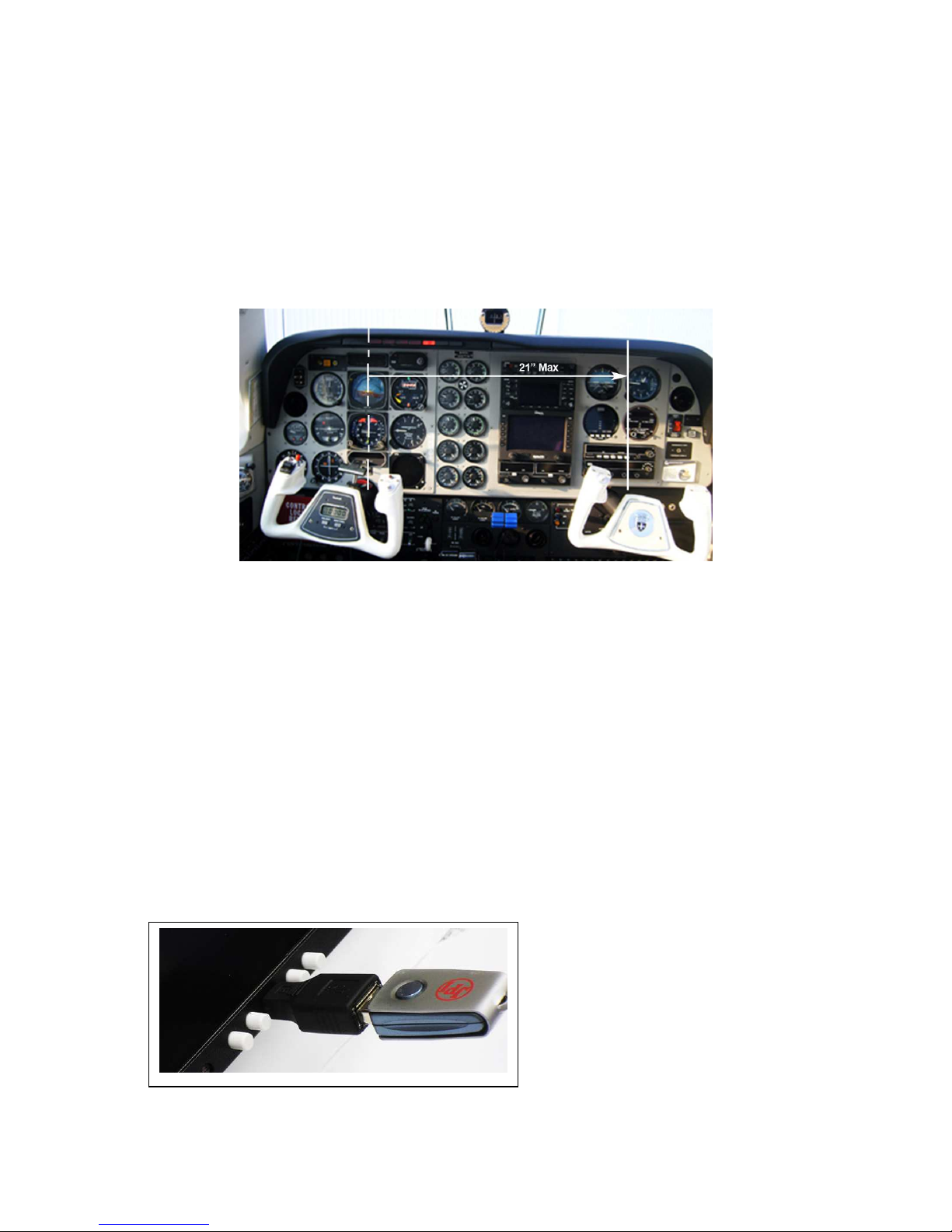
The display is best located within the natural scan and easy reach of the pilot. The recommended mounting location
is defined as the distance from the vertical centerline of the Primary Flight Instruments to the outer edge of the
further most gauge displayed on the EDM.
HORIZONTAL ORIENTATION:
The EDM display may be mounted from the vertical centerline of the Primary Flight Instrument “T” to a maximum of
21” to the further most gauge of the EDM display and to the left of the centerline as much as needed.
VERTICAL ORIENTATION:
The EDM display is to be mounted within +/- 10” from the horizontal centerline of the Primary Flight
Instrument “T”. The installer should insure that the EDM display is not obstructed by either
the glare shield or the control wheel.
The installing A&P and IA must insure that the installation location complies with the viewing angle requirements
listed above.
6. EDM-900/930 Key information installation
Aircraft specific configuration information is loaded differently on both the EDM-900 and the EDM-930. The
configuration data is the same for both instruments. The data for the EDM-900/930 is loaded via the mini USB port
on the EDM-900 and a standard USB port for the EDM-930.
Otros manuales para EDM-900
2
Este manual sirve para los siguientes modelos
1
Tabla de contenidos
Otros manuales de GPS de J.P. Instruments