IVAR SFWC Manual de usuario

Fresh Water Controller SFWC
Installation and operating instructions
Read carefully before installation, commissioning and operation

Contents
A. - Safety Instructions 3
A.1. - EC declaration of conformity 3
A.2. - General instructions 3
A.3. - Explanation of symbols 3
A.4. - Changes to the unit 4
A.5. - Warranty and liability 4
B. - Description of Controller 5
B.1. - Specications 5
B.2. - Temperature resistance table 5
B.3. - About the controller 6
B.4. - Scope of supply: 6
B.5. - Disposal and pollutants 6
B.6. - Hydraulic variants 7
C. - Installation 8
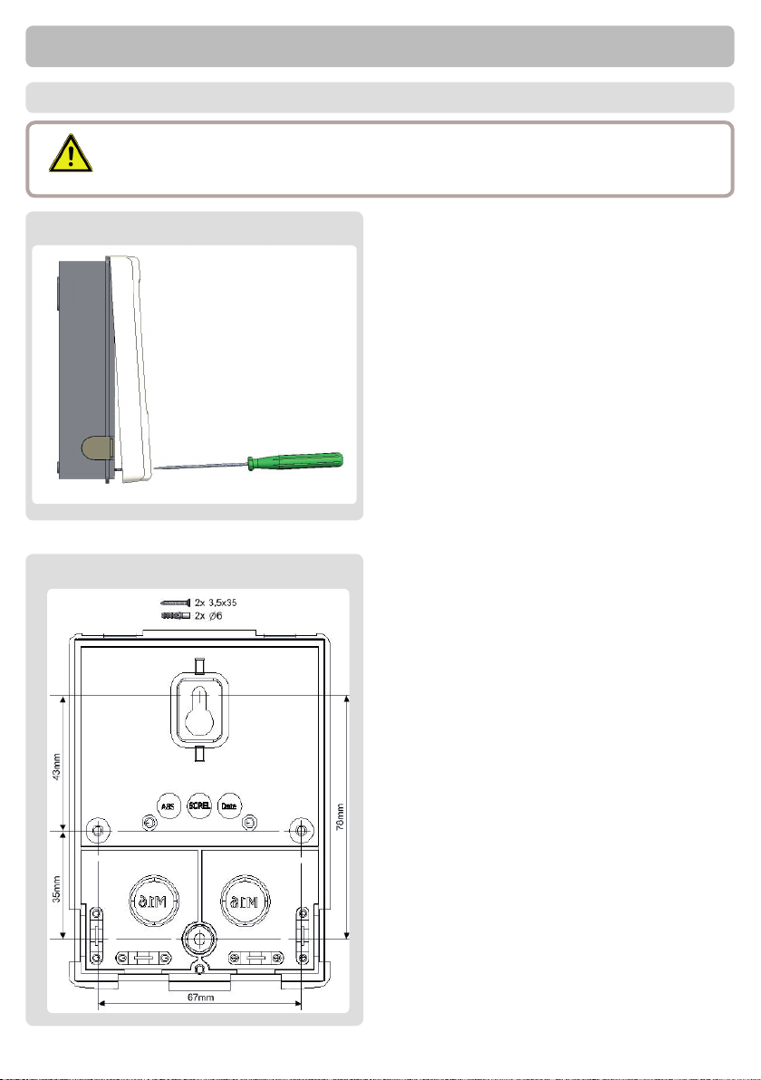
C.1. - Wall installation 8
C.2. - Electrical connection 9
C.1. - Installing the temperature sensors 11
D. - Terminal connection diagrams 12
E. - Operation 13
E.1. - Display and input 13
E.2. - Menu sequence and menu structure 14
F. - Parametrisation 15
F.1. - Commissioning help 15
F.2. - Free commissioning 15
F.3. - Calibration 16
1. - Measurements 17
2. - Statistics 18
2.1. - Operating hours 18
2.2. - Heat output 18
2.3. - Graphic overview 18
2.4. - Error messages 18
2.5. - Reset / clear 18
3. - Operating Mode 19
3.1. - Automatic 19
3.2. - Manual 19
3.3. - Off 19
4. - Settings 20
4.1. - Tset 20
4.2. - Tmax 20
4.3. - VFS -Type 20
4.4. - Circulation 21
4.4.1. - Circulation 21
4.4.2. - Circ. Tmin. 21
4.4.3. - Circ. hysteresis 21
4.4.4. - Circ. maximum Flow rate 21
4.4.5. - Circulation period 22
4.4.6. - Tap support 22
4.4.7. - Min storage temp 22
4.4.8. - Tap support calibration 22
4.10. - Comfort 22
5. - Protections / Protective functions 23
5.1. - Antilegionella 23
5.2. - Limescale Protection 24
5.3. - Discharge Protection 24
5.4. - Seizing Protection 24
6. - Special Functions 25
6.1. - Pump menu 25
6.1.1. - Type of pump 25
6.1.2. - Pump 25
6.1.3. - Output Signal 25
6.1.4. - 0-10V off / PWM off 25
6.1.5. - 0-10V on / PWM on 26
6.1.6. - 0-10V Max / PWM Max 26
6.1.7. - Show signal 26
6.2. - Speed control R1 / R2 27
6.2.1. - Max. speed 27
6.2.2. - Min. speed 27
6.3. - Relay functions 27
6.3.1. - Always on 27
6.3.2. - Circulation 27
6.3.3. - Parallel operation V1 27
6.4. - Sensor calibration 28
6.5. - Commissioning 28
6.6. - Factory settings 28
6.7. - Time & Date 28
6.8. - Daylight saving time 29
6.9. - Sleep mode 29
6.10. - Temperature unit 29
7. - Menu Lock 30
7.1. - Menu lock 30
7.2. - Expert mode 30
8. - Service Values 31
9. - Language 32
Z.1 Malfunctions with Error Messages 33
Z.2 Replacing the Fuse 34
Z.3. Maintenance 35

3
Safety Instructions
A.1. - EC declaration of conformity
By af xing the CE mark to the unit the manufacturer declares that the SFWC conforms to
the following relevant safety regulations:
- EC low voltage directive 2006/95/EC
- EC electromagnetic compatibility directive 2004/108/EC
Conformity has been veri ed and the corresponding documentation and the EC declaration
of conformity are kept on le by the manufacturer.
A.2. - General instructions
It is essential that you read this!
These installation and operating instructions contain basic instructions and important infor-
mation regarding safety, installation, commissioning, maintenance and the optimal use of the
unit. Therefore these instructions must be read completely and understood by the installation
technician/ specialist and by the system user before installation, commissioning and opera-
tion of the unit.The valid accident prevention regulations, VDE regulations, the regulations
of the local power utility, the applicable DIN-EN standards and the installation and operating
instruction of the additional system components must also be observed. The controller does
not under any circumstances replace any safety devices to be provided by the customer!
Installation, electrical connection, commissioning and maintenance of the unit may only be
carried out by specialists who possess the appropriate training.
For the user: Make sure that the specialist gives you detailed information on the function and
operation of the controller. Always keep these instructions in the vicinity of the controller.
A.3. - Explanation of symbols
Caution
Information which is especially important for the function and optimal use of
the unit and the system.
Caution
Failure to observe these instructions can result in destruction of
the unit or the system, or damage to the environment.
Danger
Failure to observe these instructions can result in serious damage
to health such as scalding, or even life-threatening injuries.
Failure to observe these instructions can result in danger to life from electric
voltage.
Danger

4
A.4. - Changes to the unit
A.5. - Warranty and liability
The controller has been manufactured and tested with regard to high quality
and safety requirements. The unit is subject to the statutory guarantee period
of two years from the date of sale.
The warranty and liability shall not include, however, any injury to persons or
material damage that is attributable to one or more of the following causes:
- Failure to observe these installation and operating instructions
- Improper installation, commissioning, maintenance and operation
- Improperly executed repairs
- Unauthorised structural changes to the unit
- Installation of additional components that have not been tested together with the unit
- Any damage resulting from continued use of the unit despite an obvious defect
- Failure to use original spare parts and accessories
- Use of the device for other than its intended purpose
- Operation above or below the limit values listed in the speci cations
- Force majeure
- Changes, additions to or conversion of the unit are not permitted without the written permis-
sion from the manufacturer
- It is likewise forbidden to install additional components that have not been tested together
with the unit
- If it becomes clear that safe operation of the unit is no longer possible, for example because
of damage to the housing, then turn the controller off immediately
- Any parts of the unit or accessories that are not in perfect condition must be exchanged
immediately
- Use only original spare parts and accessories from the manufacturer.
- Markings made on the unit at the factory must not be altered, removed or made illegible
- Only the settings actually described in these instructions may be made on the controller
Safety instructions
Danger
Changes to the unit can compromise the safety and function of the
unit or the entire system.

5
Description of controller
B.1. - Specications
B.2. - Temperature resistance table for Pt1000 sensors
°C 0 10 20 30 40 50 60 70 80 90 100
Ω1000 1039 1077 1116 1155 1194 1232 1270 1308 1347 1385
Electrical specications:
Mains voltage 230VAC +/-10%
Mains frequency 50 - 60Hz
Power consumption 1,5W - 2,0W
Internal fuse 2A slow blow 250V
Protection category IP40
Protection class II
Overvoltage Category II
Degree of Pollution Category II
mechanisches Relais 460VA für AC1 / 460W für AC3 1
0-10V output, tolerance 10%, 10 k Ω load or
PWM output freq. 1 kHz, level 10 V
1
PT1000 sensor input measuring range -40°C to 300°C 2
Permissible cable length of sensors and appliances:
Sensor S1 and S2 <10m
PWM / 0...10V <3m
mechanical relay <10m
VFS <3m
Permissible ambient conditions:
Ambient temperature
for controller operation 0°C...40°C
for transport/storage 0°C...60°C
Air humidity
for controller operation max. 85% rel. humidity at 25°C
for transport/storage no moisture condensation permiddled
Other specications and dimensions
Housing design 2-part, ABS plastic
Installation methods Wall installation, optionally panel installation
Overall dimensions 115mm x 86mm x 45mm
Aperture dimensions 108mm x 82mm x 25.2mm
Display Fully graphical display, 128 x 128 dots
Operation 4 entry keys

6
B.3. - About the controller
The Fresh water controller SFWC facilitates ef cient use and function control through of
your fresh water system. Tap water temperature is regulated fast and precise. The device is
impressive most of all for its functionality and simple, almost self-explanatory operation. For
each step in the input process the individual entry keys are assigned to appropriate func-
tions and explained. The controller menu contains headwords for the measured values and
settings, as well as help texts or clearly-structured graphics.
Important characteristics of the SFWC:
- Depiction of graphics and texts in a lighted display
- Simple viewing of the current measurement values
- Analysis and monitoring of the system by means of statistical graphics,etc.
- Extensive setting menus with explanations
- Menu block can be activated to prevent unintentional setting changes
- Resetting to previously selected values or factory settings
B.4. - Scope of supply:
- Fresh water controller SFWC
- replacement fuse 2A slow-blow
- Installation and operating instructions SFWC
Optionally contained depending on design/order:
- Pt1000 temperature sensor and Vortex Flow Sensor
B.5. - Disposal and pollutants
The unit conforms to the European RoHS directive 2011/65/EU for the restriction of the use
of certain hazardous substances in electrical and electronic equipment.
Caution
The unit must not under any circumstances be disposed of with ordinary
household refuse. Dispose of the unit only at appropriate collection points or
ship it back to the seller or manufacturer.
Description of controller

7
B.6. - Hydraulic variants
Description of controller
The following illustrations should be viewed only as schematic diagrams
showing the respective hydraulic systems, and do not claim to be complete.
The controller does not replace safety devices under any circumstances.
Depending on the speci c application, additional system components and
safety components may be mandatory, such as check valves, non-return
valves, safety temperature limiters, scalding protectors, etc., and must there-
fore be provided.
Caution
Basic scheme Additional function circulation

8
Installation
C.1.1
C.1.2
C.1 Wall installation
1.Unscrew cover screw completely
2.Carefully pull upper part of housing from
lower part.
3.Set upper part of housing aside, being
sure not to touch the electronics when
doing so.
4. Hold the lower part of the housing
(C.1.2) up to the selected position and
mark the 2 mounting holes. Make sure
that the wall surface is as even as possi-
ble so that the housing does not become
distorted when it is screwed on.
5. Using a drill and size 6 bit, drill 2 holes
at the points marked on the wall and push
in the plugs. Also possible is the installati-
on with 4 drill holes.
6. Insert the upper screw and screw it in
slightly.
7. Fit the upper part of the housing and
insert the other screws.
8. Align the housing and tighten the
screws.
Caution
Install the controller only in dry areas and under the ambient conditions
described under 2.1 “Speci cations”. Carry out the following steps:

9
Installation
Caution
Danger
Caution
Caution
C.2 Electrical connection
Before working on the unit, switch off the power supply and secure
it against being switched on again! Check for the absence of power!
Electrical connections may only be made by a specialist and in
compliance with the applicable regulations.
Do not use the controller if the housing shows visible damage.
Low-voltage cables such as temperature sensor cables must be routed
separately from mains voltage cables. Feed temperature sensor cables
only into the left-hand side of the unit, and mains voltage cables only
into the right-hand side.
The customer must provide an all-pole disconnecting device, e.g. a
heating emergency switch.
The cables being connected to the unit must not be stripped by more
than 55mm, and the cable jacket must reach into the housing just to the
other side of the strain relief.
We recommend the use of exible cables to ease the installation in the
clamp room.
Caution
1.Select necessary program/hydraulics
(see section D)
2. Strip cables by 55mm max., insert, t
the strain relief devices, strip the last
9-10 mm of the wires. (Fig. C.2.1)
3.Open controller as described under g.
C.1.1, insert cables and install strain
reliefs
4.Install PE terminal block (see g. 2.1.a).
C.2.1
C.2.1.a

10
Installation
5. Connect the female connector block ‘s
clamp connections as described in the
terminal connection plans. When using
stranded cables, use a small screw dri-
ver and push the orange buttons while
inserting (see g. C.2.1.c). When using
solid cable or end splice, just push the
cables in (see g. C.2.1.d).
6. Plug Female connectors into onboard
headers.
7. Hinge the upper part of the casing on
the top of the lower part and close the
casing gently.
8. Fasten with screw.
9. Switch on mains voltage and place
controller in operation.
C.2.1.e
C.2.1.c
C.2.1.d
screw driver
C.2.1.f
To remove the female connector block
from the header, carefully bend the latch
on the header.
Caution: The latch breaks easily.
Tabla de contenidos
Otros manuales de Controladores de IVAR


