Isolite E3-MAC Series Manual de usuario

1KW -12.5KW
SINGLE PHASE
MODELS
1KW MODEL
SHOWN
ISOLITE –THE EMERGENCY LIGHTING EXPERTS
31 Waterloo Avenue Berwyn, PA 19312 WWW.ISOLITE.COM
IMPORTANT SAFEGUARDS
When using electrical equipment, basic safety precautions should always be followed
including the following:
READ AND FOLLOW ALL SAFETY INSTRUCTIONS
A. Do not use outdoors
B. Do not mount near gas or electric heaters.
C. Use caution when servicing batteries. Battery acid can cause burns to skin and
eyes. If acid is spilled on skin or in eyes, flush acid with fresh water and
contact a physician immediately.
D. Equipment should be mounted in locations and at heights where it will not
readily be subjected to tampering by unauthorized personnel.
E. The use of accessory equipment not recommended by the manufacturer may
cause an unsafe condition.
F. Do not use this equipment for other than intended use.
This unit contains lethal voltages. There are no user serviceable parts inside. Only
authorized service personnel are to be used for service.
SAVE THESE INSTRUCTIONS
The installation and use of this product must comply with all national, state, municipal
or local codes that apply. Please read this manual thoroughly before installing and
operating the E3-MAC Series central inverter system. For assistance please call ISOLITE
technical support at 800-967-5573 and speak to a technician during normal business
hours (EST).
Installation / Operation Manual
Emergency Lighting Central Inverter System
E3-MAC Series by

TABLE OF CONTENTS
2| INSTALLATION / OPERATION MANUAL
1.0 Introduction
1.1 Mechanical Design Features
1.2 Electrical Design Features
2.0 Receiving and Storage
2.1 Inspection
2.2 Storage
3.0 Installation
3.1 Location
3.2 Operating Environment
3.3 Ventilation
3.4 Clearance
3.5 Floor Preparation
3.6 Cabinet Configurations
4.0 AC Connections
4.1 Removing the AC Breaker cover
4.2Installing the Input Wires
4.3Installing the Output Wires
4.4Special Options
5.0 Battery and DC Connections
5.1 Battery Inspection
5.2 Battery Installation
5.3 DC Voltage of System
5.4 Battery Wiring Diagram(s)
6.0 Startup and Shutdown
Procedures
6.1 Startup Procedure
6.2 Shutdown Procedure
7.0 System Operation
7.1 Startup Mode
7.2 Battery Charging Mode
7.3 Inverter (Battery Discharge)
Mode
7.4 Normally-On Output
7.5 Normally-Off / Switched Output
8.0 Specifications
9.0 Warranty
9.1 Technical Service and Support
9.2 Return Material Authorization
(RMA)
10.0 Man Machine Interface (MMI)
10.1 Introduction
10.2 System Test Button
10.3 Alarm Silence Button
10.4 Keypad and Display Features
10.5 SD Card
10.6 USB Slot
10.7 Main Menu
10.8 Meter Menu
10.9 Alarm Menu
10.10 Event Log
10.11 Test Log
10.12 Alarm Log
10.13 User Menu
User Menu Navigation
11.0 Maintenance and Service
11.1 Battery Maintenance
11.2 Battery Replacement
12.0 Web Interface

1.0 INTRODUCTION
The E3-MAC Central Inverter System integrates the latest power electronics and
microprocessor technology and produces a pure sine wave power output intended for
use in Emergency Lighting. The system is very efficient on-line and typically has a
standby power loss of only 2 percent of the systems total capacity. This high efficiency
and the ability to turn lighting loads on and off using the optional switched load outputs
make it ideal for energy saving and green initiatives. It is UL-924 compliant for Self-
Testing and Self Diagnostic which automatically performs internal tests and then records
them in its backup logs. The MMI (Man Machine Interface) consists of a 5-button
keypad and backlit LCD display which is very powerful and feature rich. Users can access
all stored logs and diagnostic tools such as meter functions, they can also change alarm
functions and much more.
1.1 Mechanical Design Features
This product was designed having the electrical installer in mind. Batteries are Front
Access type which simply slide into the cabinet and connect with Busbar jumpers. They
are easy to install, safe and less prone to installation errors. The AC connections are also
easily made with the contractor landing the inputs and outputs to either Circuit
Breakers, terminals of busbars. Contractor piping for conduit is easily accomplished with
multi-sized knockouts on both sides and tops of the cabinet so wires can easily run into
the cabinet and connected to ground bars, neutral bars and circuit breakers.
The machine has an attractive Powder Painted 14 gauge Cold Rolled Steel construction
with no visible outside bolts or rivets. Internally, it has all galvanized or painted steel
parts for all the modules and shelves that resist corrosion and provide durability and
high quality.
1.2 Electrical Design Features
Through the use of Pulse Width Modulation (PWM) and the latest IGBT and MOSFET
technology, the E3-MAC Series can produce a pure sine-wave output which is
compatible with all types of lighting loads. A high crest factor of up to 4X is extremely
beneficial for high-inrush loads and also ideal for bringing Normally-Off lighting loads on
from a cold start. Since the active PWM regulation scheme produces a very low THD
waveform, the E3-MAC Series can power up even the most demanding loads driving its
output with power factor capabilities ranging from 0.5 leading to 0.5 lagging.
Adding to the versatility are the multiple output types of Normally-On, Normally-Off
and Switched. The batteries are charged by a temperature compensated charger
integrated into a bi-directional converter. A three-rate charging scheme and bi-
directional converter topology ensures maximum float life and minimal ripple current on
the batteries.
E3-MAC SERIES | 3

WARNING –The maximum storage time from shipment to initial
charge is 6 months for batteries stored at ambient temperatures no
warmer than 77°F (25°C). For storage temperatures greater than
77°F (25°C) the batteries must be recharged one (1) month sooner
for every 5°F (3°C) increase above 77°F (25°C).
2.0 RECEIVING AND STORAGE
2.1 Inspection
The E3-MAC Series central inverter and batteries are shipped together unless specified
with the “ship-less batteries” option code(-UP). Upon arrival, please inspect the
contents to ensure that no shipping damage has occurred. This is especially important
with batteries –ensure that there are no cracks or leaks. If any damage has occurred,
notify the shipping carrier immediately and submit a damage claim.
WARNING - NEVER use a physically damaged battery as this may cause an unsafe
condition.
2.2 Storage
Storage temperature before the installation is critical for the battery life expectancy
and warranty. Store the system indoors in a clean, dry and cool location. Storage at
higher temperatures will result in accelerated rates of self-discharge and possible
deterioration of battery performance and life.
Storage times exceeding the above may result in plate sulfation, which may adversely
affect electrical performance and expected life.
Failure to install and charge the batteries as noted
VOIDS the battery’s warranty
DANGER -Batteries present a risk of electrical shock and high short circuit current. Do
not smoke, cause a flame or spark in the immediate area of the batteries. Use proper
lifting means when moving batteries and wear all appropriate safety clothing and
equipment.
4| INSTALLATION / OPERATION MANUAL
3.0 INSTALLATION
3.1 Location
NEC article 700 EMERGENCY CIRCUITS should be referenced for proper installation of a
central inverter system. Article 700 dictates that unit must be mounted in a permanent
location. Choose a cool dry place with normal ventilation and one which will allow easy
access for testing and maintenance. Avoid a location which could allow vandalism and
tampering. Avoid areas that would prohibit visual contact with the heads-up LED status
displays.
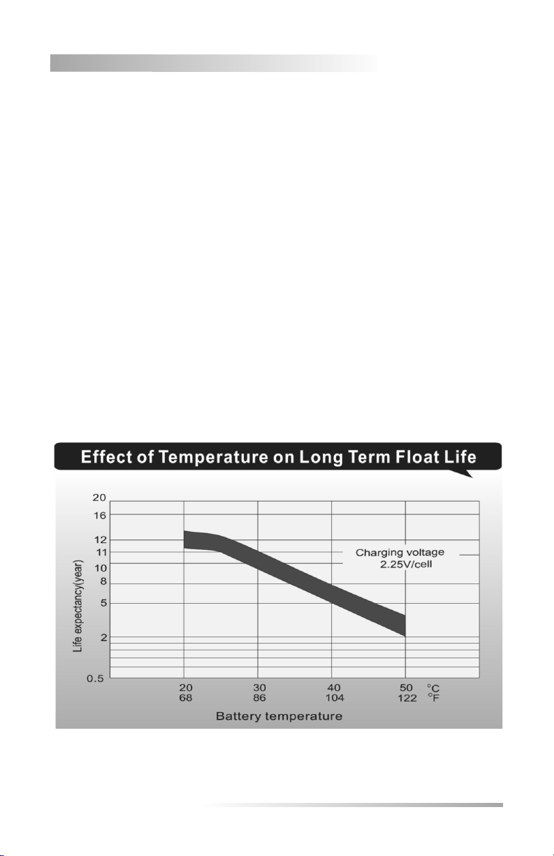
3.2 Operating Environment
Choose a location that is controlled between 20 and 30 °C for optimum battery life.
E3-MAC Series is UL924 listed between 20 and 30 °C due to the battery discharge
performance results. Colder temperatures decrease the batteries discharge duration (90
Minutes is required per UL924 and NEC Article 700) and warmer temperatures will
adversely affect battery life. The optimal temperature of the E3-MAC Series system will
be 25°C / 77°F and all measures should be made to keep the batteries in this
temperature zone. Temperature -vs- Life expectancy is shown below.
E3-MAC SERIES | 5

3.3 Ventilation
Because the E3-MAC Series uses a maintenance-free sealed valve regulated lead acid
(VRLA) battery, no special ventilation is required. Spaces normally occupied by humans
with either natural or forced ventilation allowing at least 1 to 2 air exchanges per hour is
recommended. Choose a mounting location that is clean and dust free. Do not install in
areas where there is particulate or high pollution degree from heavy industrial
machinery, corrosive chemicals or welding or plasma cutting environments etc.
3.4 Clearance
Air ventilation is through the front surface so there are no clearance requirements for
the top, back or sides of the cabinet. However, the NEC code does require an
unobstructed 3 ft. of clearance in front of the cabinet (i.e. electrical panels).
3.5Floor Preparation
The mounting floor should be smooth and level so that the cabinet is not skewed or
twisted which would prevent the systems front door from being easily removed. Final
system leveling should be accomplished by shimming the cabinets corners so that the
front door can easily be removed for service. Floor mounting holes are provided in the
cabinet’s base and will accommodate up to a 3/8” mounting bolt. All 4 mounting holes
should be secured with bolts due to the weights of the cabinet(s) and associated
batteries. We recommend concrete wedge anchors such as the Hilti brand Wedge
Anchor series Kwik Bolt TZ or equivalent.
3.6Cabinet Configurations
There are 4 cabinet sizes/configurations for the E3-MAC Series. Electrical Knock Outs
(EKO’s) are provided on three surfaces. Ensure all metal conduit is secured and
tightened creating a good connection to earth ground. Use an Ohm-Meter to check that
continuity between conduit and protective earth ground has been established.
Seismic bracing is available for the E3-MAC Series. Please see Isolite.com for details of
seismic dimensions and configurations.
Note –Cabinet sizes and construction may change due to optional features such as
mixed voltages which require Isolation Transformers and/or Auto-Transformers.
All systems are shipped with a Contractors Guide for each model. This should be
referred to in the installation process since there may be more details available.
WARNING –Drilling into cabinet may void warranty if metal filings causes unit failure.
6| INSTALLATION / OPERATION MANUAL

SIZE 1
1KW Model
3.6 Cabinet Configurations (cont.)
Size 1 1KW
Size 2 1.6KW, 2.2KW, 2.8KW, 3.0KW
Size 3 4.0KW, 5.0KW, 6.0KW
Size 4 8.0KW, 10.0KW, 12.5KW
Note –Standard cabinet configurations for all sizes are shown. Other cabinet
configurations may be used when optional features are provided such as mixed
Input/Output voltages which requires isolation or auto-type transformers. These options
require additional cabinet space which may increase size.
E3-MAC SERIES | 7

SIZE 2
1.6KW thru 3.0KW Models
8| INSTALLATION / OPERATION MANUAL

SIZE 3
4.0KW thru 6.0KW Models
E3-MAC SERIES | 9

SIZE 4
8.0 KW thru 12.5 KW Models
10 | INSTALLATION / OPERATION MANUAL
Otros manuales para E3-MAC Series
1
Este manual sirve para los siguientes modelos
11
Tabla de contenidos
Otros manuales de Inversor de Isolite


