Instrumentation GDD GRx8mini Manual de usuario

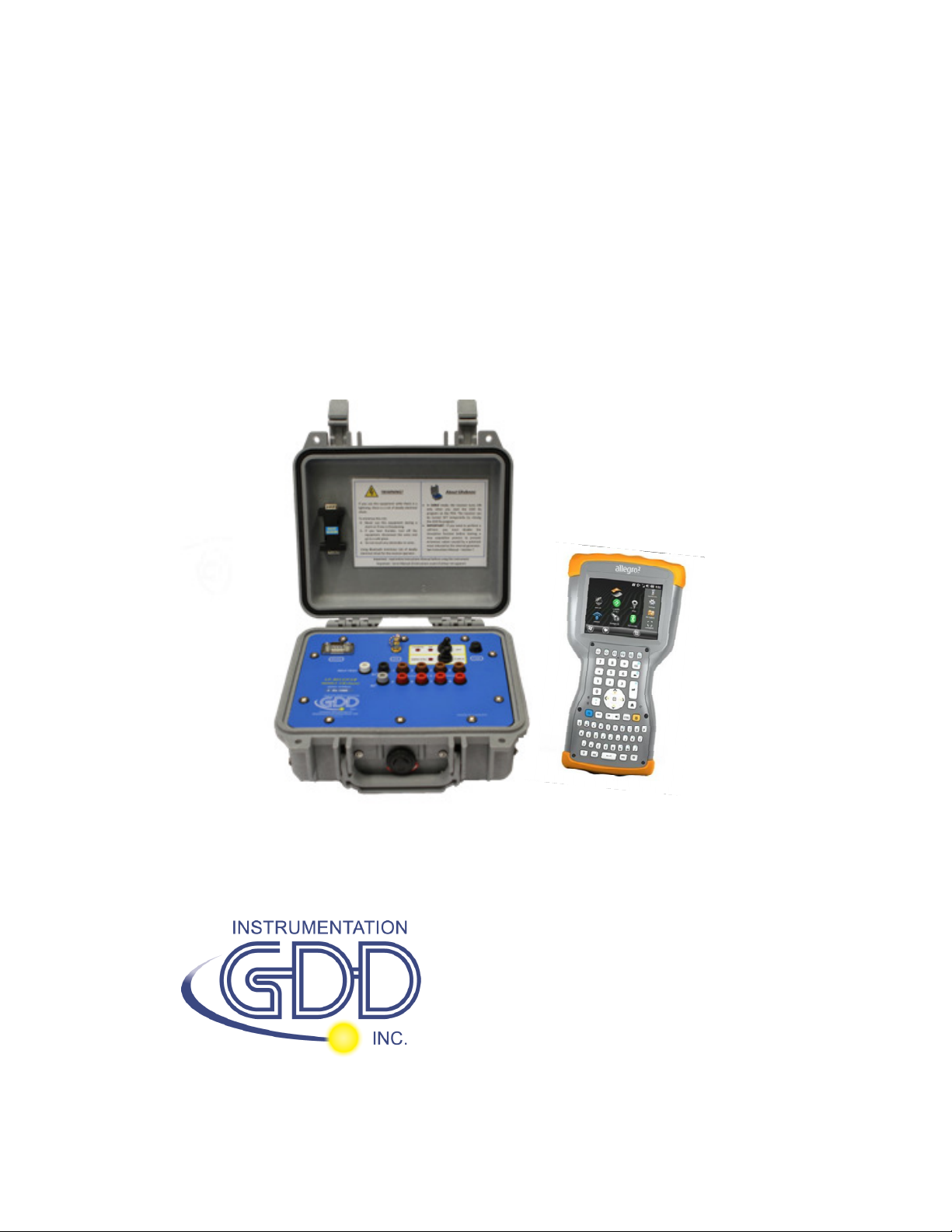
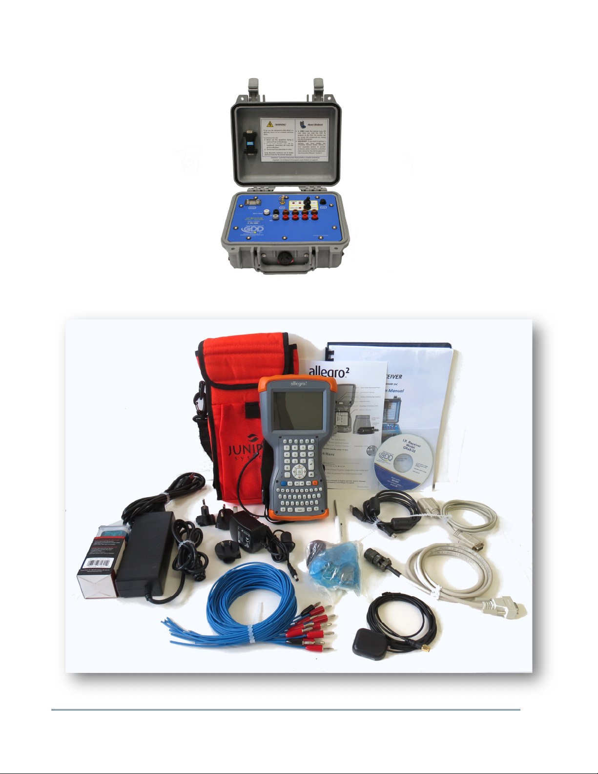
IP RECEIVER
Model GRx8mini
Instruction Manual
860 boul. de la Chaudière, suite 200
Québec (QC), Canada, G1X 4B7
Tel.: +1 (418) 877-4249
Fax: +1 (418) 877-4054
E-Mail: gdd@gdd.ca
Web site: www.gdd.ca

Instrumentation GDD Inc. 2018-04-06 Page 2
Visit our web site at:
www.gdd.ca
To:
•Discover GDD s new products.
•Download the latest version of the Instruction Manual.
•Comment on or ask questions about products.

Instrumentation GDD Inc. 2018-04-06 Page 3
1. Introduction ............................................................................................................................. 5
2. 5
2. Receiver Accessories ................................................................................................................ 6
3. Receiver Components............................................................................................................... 8
4. Power .................................................................................................................................... 11
5. Quic Start Guide ................................................................................................................... 13
6. RS232/Bluetooth Communication ........................................................................................... 21
7. Cold weather and harsh environments tips ............................................................................. 22
8. Tools Menu ............................................................................................................................ 23
8.1 Config option ..................................................................................................................... 25
8.1.1 Setup ................................................................................................................................. 25
8.1.2 Position ............................................................................................................................. 27
8.1.3 Windows ............................................................................................................................ 29
8.1.4 Synchronization ................................................................................................................. 34
8.2 Special option .................................................................................................................... 38
8.2.1 Reinit ................................................................................................................................ 38
8.2.2 Simulation ......................................................................................................................... 39
8.2.3 Signal Processing Options .................................................................................................. 43
8.2.4 Battery type ...................................................................................................................... 44
8.2.5 Open Port ...................................................................................................................... 45
8.3 Show option ...................................................................................................................... 47
8.3.1 Hot eys.............................................................................................................................. 47
8.3.2 Pseudosection .................................................................................................................... 48
8.3.3 Signal ................................................................................................................................. 50
8.3.3.1 Tools menu........................................................................................................................... 52
8.3.3.1.1 Auto Correction ................................................................................................... 52
8.3.3.1.2 Restore ................................................................................................................ 52
8.3.3.1.3 PAUSE/GO ........................................................................................................... 53
8.3.4 Contact and Noise .............................................................................................................. 53
8.3.5 Vp and Cycle ...................................................................................................................... 54
8.3.6 Show M and errM .............................................................................................................. 55
8.3.7 Decay Curve ....................................................................................................................... 56
8.3.8 Show Windows .................................................................................................................. 57
8.3.9 Show Sp ............................................................................................................................. 58
8.4 Raw Data Option................................................................................................................ 59
8.4.1 Chec GPS .......................................................................................................................... 59
8.4.2 Start Recording (raw data) .................................................................................................. 62
8.5 Memory Option ................................................................................................................. 65
8.5.1 Display Reading .................................................................................................................. 65
8.5.2 History ............................................................................................................................... 66
8.5.3 Bac Mem .......................................................................................................................... 67
8.5.4 Clear Mem ......................................................................................................................... 68
8.5.5 Save File ............................................................................................................................. 69
8.6 About Option ..................................................................................................................... 73
TABLE OF CONTENTS

Instrumentation GDD Inc. 2018-04-06 Page 4
9. Transferring data ................................................................................................................... 74
9.1 ActiveSync ......................................................................................................................... 74
9.1.1 Installation and settings ..................................................................................................... 74
9.1.2 Establishing connection with a des top PC .......................................................................... 75
9.1.3 Transferring file(s) from the Allegro
2
to a des top PC .......................................................... 76
9.2 Windows Mobile Device Center .......................................................................................... 78
9.2.1 Installation and settings ..................................................................................................... 78
9.2.2 Establishing connection with a des top PC .......................................................................... 79
9.2.3 Transferring file(s) from the Allegro
2
to a des top PC .......................................................... 80
9.3 USB connection .................................................................................................................. 82
10. Bluetooth configuration ......................................................................................................... 84
11. GDD Rx software update ........................................................................................................ 88
12. Troubleshooting ..................................................................................................................... 90
13. Specifications ......................................................................................................................... 97
13.1 General specifications ............................................................................................................ 97
13.2 Technical specifications .......................................................................................................... 97
14. Technical help ........................................................................................................................ 99
Annex 1 – Geometrical parameters ................................................................................................ 100
Annex 2 – 3D Survey ..................................................................................................................... 106
Annex 3 – Field survey setup ......................................................................................................... 118
Annex 4 – Example Dump File (.gdd format) .................................................................................. 140

Instrumentation GDD Inc. 2018-04-06 Page 5
1. Introduction
The highly sensitive GDD IP Receiver GRx8mini is a compact unit designed for high productivity
resistivity and time-domain induced polarization (IP) surveys in mineral exploration, groundwater
exploration, geotechnical investigations and other related fields. It features high capabilities
allowing it to work in any field conditions. It can be configured for multi-pole or multi-dipole
reception. The receiver uses a handheld field PC to process data acquisition and the software can
easily be updated via internet.
Characteristics:
•Reception poles/dipoles: 8 poles/dipoles for dipole-dipole, pole-dipole or pole-pole arrays.
•Programmable windows: The GRx8mini offers twenty fully programmable windows for
higher flexibility in defining the IP decay curve.
•User modes available: Arithmetic, logarithmic, semi-logarithmic, Cole-Cole and user
defined.
•IP display: Chargeability values, Apparent Resistivity, IP decay curves and pseudosections
can be displayed in real time thanks to the TFT VGA screen. Before data acquisition, the
GRx8mini can be used as a one channel graphic display for monitoring the noise level and
checking the primary voltage waveform through a continuous display process.
•Internal memory: Capacity to store up to 64 000 readings for 8 poles/dipoles, memory
expandable to 512 000 readings on the field PC. Each reading includes the full set of
parameters characterizing measurements. Data is stored on flash type memory that does
not require any lithium battery for safeguard purposes.
•Full wave data with IP Post-Processing software: The GRx8mini records and saves the full
wave data (*.mem file). This raw data can be imported, visualized and processed using
GDD's IP Post-Processing software.
2.

Instrumentation GDD Inc. 2018-04-06 Page 6
2. Receiver Accessories
A 1x IP receiver, model GRx8mini
B 1x UART programming adapter (Boot Loader)
C 1x Allegro
2
field computer with a 10.6Ah rechargeable Li-Ion battery and an
adjustable hand strap
D 1x Allegro
2
capacitive stylus with tether
E 1x Allegro
2
Holster case
F 1x Allegro
2
wall charger with international plug kit
G 1x IP receiver charger (power supply)
H Blue cables with black banana connectors or red banana connectors
I 1x Standard serial communication cable
J 1x Rugged serial communication cable (Amphenol connector)
K 2x Micro USB Communication Cables
L 1x External GPS antenna (SMA connector)
M 1x Input signals connector (14 positions) - Optional
N 1x Allegro
2
Quick Start Guide
O 1x GDD Instruction manual
P 1x Screwdriver
Q 1x IP Receiver documentation CD/USB Stick
Not shown on the illustration:
1x Blue carrying case
1x GDD-RTE01 communication box with USB cable (optional accessory)
Optional accessories:
GDD-BP02 External battery pack (for 8, 10 to 16 channels receivers)
GDD-RTE01 communication box with USB cable
Input signals connector (14 positions)

Instrumentation GDD Inc. 2018-04-06 Page 7
A
B
C
D
F
G
H
I
J
K
L
M
optional
N
O
P
Q
E

Instrumentation GDD Inc. 2018-04-06 Page 8
3. Receiver Components
The GRx8mini components are described in this section.
A - RS-232 connector - 9 pin serial communication port
This connector is used to connect the serial communication cable between the Allegro
2
and
the GRx8mini.
B - GPS Connector
This connector is used to connect an external GPS antenna (SMA).
C - CABLE/WIRELESS switch
This switch is used to select CABLE (RS-232) or WIRELESS (Bluetooth) communication with
the field PC. The red light indicates that the switch is in the WIRELESS position.
A
B
C
D
E
F
G
H

Instrumentation GDD Inc. 2018-04-06 Page 9
D - ON/OFF switch
This switch is used to turn the GRx8mini ON. The ON red light indicates that the GRx8mini is
ON.
E - FUSE
This fuse prevents damages that could be caused by a defective charger.
Replacement fuse: 5x20mm 6A 125V fast action
F - SELF-TEST terminal
This terminal is used to perform a self-test.
G - R1 and R2 terminals
In pole configuration, the reference terminals (R1 and R2) are the infinite electrodes. In
dipole configuration, the reference terminal is the first electrode in differential with the
second electrode.
H - NUMBERED terminals
These terminals are referenced to the Ref terminal (Ref is infinity in pole configuration). In
dipole configuration, the numbered terminals are differential terminals.
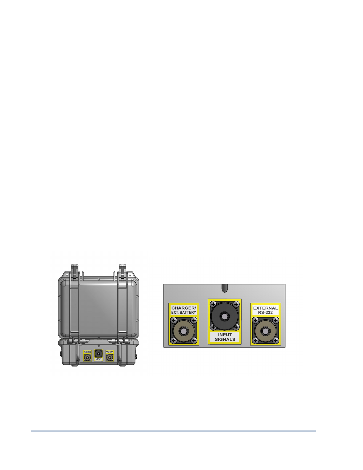
I - CHARGER/EXT. BATTERY connector
This connector is used to charge the receiver s batteries. It can also be used to connect an
external battery pack provided by GDD (optional). The CHARGE red light on the top of the
receiver indicates that the internal batteries are charging. The light turns off when the
batteries are fully charged.
I
K
J

Instrumentation GDD Inc. 2018-04-06 Page 10
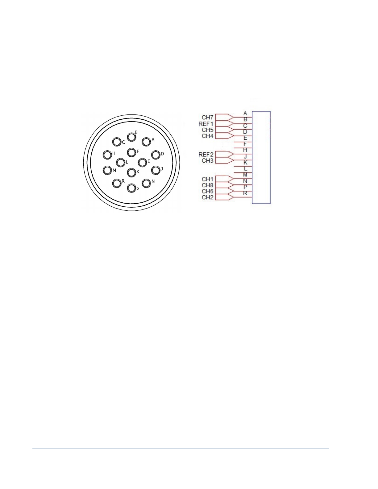
J - Input signal connector
This connector is used to connect the wires coming from the electrodes to the receiver
channels to keep the Pelican case closed while taking the readings. An optional cable mount
connector (14 pos.) can be purchased and used with the instrument.
K - RS-232 external Connector
This connector is used to connect the rugged serial communication cable (Amphenol
connector), which allows communication between the Allegro
2
and the GRx8mini receiver.
Tabla de contenidos
Otros manuales de Receptor de Instrumentation GDD