© Copyright 2020 InPower LLC
Document: OM-54 Version Code: L
Date: Oct 15, 2009 Date: Jan 8, 2020
Page 4 of 16
ETM51 Owner’s Manual
2. Mounting
Mount the ETM51 Module under the dash or on a at surface using the two mounting
holes. Ensure that you have sufcient distance to install the 36 inch DLC cable.
3. Installing the DLC Cable
Connect the two Faston terminals on the DLC cable to the ETM51 module terminals
(Yellow wire to CANH terminal and Green wire to CANL terminal). Route the cable to
the OBDII Data Link Connector and plug it in. The OBDII connector is usually located
on the lower part of the dash on the driver’s side. Using a cable tie, secure the plug
to the OBDII connector so that it will not vibrate out. We recommend routing the DLC
cable across the bottom of the plug/connector and looping the cable tie around the plug,
socket and cable to keep it out of the way.
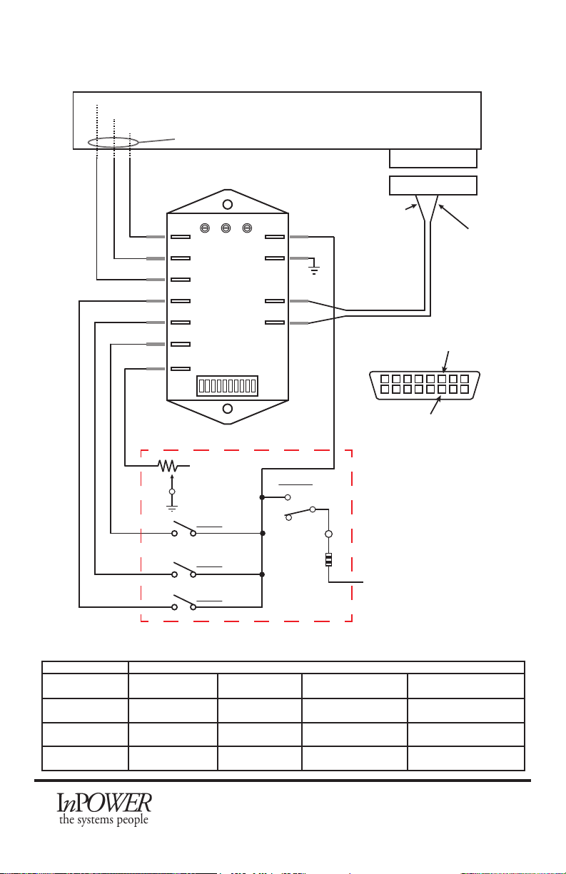
4. Wiring the Mode Selection and SEIC Controls
The ETM51 module must be wired to the Ford SEIC blunt-cut wires and to the customer-
supplied Mode Selection controls. The wiring is different for diesel and gas applications,
so please refer to the appropriate wiring diagrams on pages 6 through 16. You will also
need a good quality chassis ground (battery negative) signal and a +12 volt supply fed
from the Ignition Switch.
Note that on gas engine installations, Ford requires the +12 volt supply to be
“clean” - i.e. it should have no other loads on the same circuit that could generate
electrical noise.
4A. High Idle Speed Mode Controls
Determine the combination of fast idle speed modes you will need (up to three xed
preset speeds and/or an optional variable RPM control). If you need the optional
variable RPM Control, you will need a 10k Ohm potentiometer (VRPM). For each
desired RPM1, RPM2, and RPM3 setting, you need one switch or relay contact to select
them. You will also need to implement a Fast Idle On/Off switch.
Wire these devices as shown in the Wiring Diagram for your respective engine: Diesel
(page 6-8) or Gas (page 9-16). Make sure to have a good quality chassis ground and a
+12 volt fused supply fed from the Ignition Switch. Refer to the most current applicable
Ford Body Builders Bulletin for location of these circuits.
Note on Variable RPM control: We recommend a three or up to a ten turn 10K
potentiometer such as those available from Digikey (www.digikey.com).
4B. Ford SEIC Wiring
Install the wires between the ETM51 module and the Ford SEIC as shown in the wiring
diagrams. On most F-250 to 550 trucks from 2005 to 2016, the SEIC wires are located
above the parking break pedal, and in the case of 2017 and after, they are located on
the Passenger Side. On F650 and F750 chassis, they are located under the hood on the
passenger side. Refer to the Ford SEIC documentation for more details.
WARNING: Please refer to most current Ford Body Builder’s Bulletin for applicable
year wire colors for your vehicle.