Infoblox Infoblox-1852-A Manual de usuario

1
Contents
Introduction . . . . . . . . . . . . . . . . . . . . . . . . . . . . . . . . . . . . . . . . . . . . . . . . . . . . . . . . . . . . . . . . . . 3
Product Overview . . . . . . . . . . . . . . . . . . . . . . . . . . . . . . . . . . . . . . . . . . . . . . . . . . . . . . . . . . . . . . . . . . . . . . . . . . . . . . .3
Hardware Components. . . . . . . . . . . . . . . . . . . . . . . . . . . . . . . . . . . . . . . . . . . . . . . . . . . . . . . . . . . . . . . . . . . . . . . . . . .4
System, Environmental, and Power Specifications . . . . . . . . . . . . . . . . . . . . . . . . . . . . . . . . . . . . . . . . . . . . . . . . . . . .9
Installing an Appliance . . . . . . . . . . . . . . . . . . . . . . . . . . . . . . . . . . . . . . . . . . . . . . . . . . . . . . . .11
Rack Mounting . . . . . . . . . . . . . . . . . . . . . . . . . . . . . . . . . . . . . . . . . . . . . . . . . . . . . . . . . . . . . . . . . . . . . . . . . . . . . . . 11
Powering the Appliance . . . . . . . . . . . . . . . . . . . . . . . . . . . . . . . . . . . . . . . . . . . . . . . . . . . . . . . . . . . . . . . . . . . . . . . . 11
Cabling the Appliance to a Network . . . . . . . . . . . . . . . . . . . . . . . . . . . . . . . . . . . . . . . . . . . . . . . . . . . . . . . . . . . . . . 12
Changing Power Supplies . . . . . . . . . . . . . . . . . . . . . . . . . . . . . . . . . . . . . . . . . . . . . . . . . . . . . . . . . . . . . . . . . . . . . . 13
Accessing the Appliance . . . . . . . . . . . . . . . . . . . . . . . . . . . . . . . . . . . . . . . . . . . . . . . . . . . . . . .15
Connecting to the Appliance . . . . . . . . . . . . . . . . . . . . . . . . . . . . . . . . . . . . . . . . . . . . . . . . . . . . . . . . . . . . . . . . . . . . 16
Specifying Appliance Settings. . . . . . . . . . . . . . . . . . . . . . . . . . . . . . . . . . . . . . . . . . . . . . . . . . . . . . . . . . . . . . . . . . . 17
Infoblox GUI . . . . . . . . . . . . . . . . . . . . . . . . . . . . . . . . . . . . . . . . . . . . . . . . . . . . . . . . . . . . . . . . . . . . . . . . . . . . . . . . . 19
Infoblox CLI . . . . . . . . . . . . . . . . . . . . . . . . . . . . . . . . . . . . . . . . . . . . . . . . . . . . . . . . . . . . . . . . . . . . . . . . . . . . . . . . . . 20
Copyright Statements
© 2010, Infoblox Inc.— All rights reserved.
The contents of this document may not be copied or duplicated in any form, in whole or in part, without the prior
written permission of Infoblox, Inc.
The information in this document is subject to change without notice. Infoblox, Inc. shall not be liable for any
damages resulting from technical errors or omissions which may be present in this document, or from use of this
document.
This document is an unpublished work protected by the United States copyright laws and is proprietary to Infoblox,
Inc. Disclosure, copying, reproduction, merger, translation, modification, enhancement, or use of this document by
anyone other than authorized employees, authorized users, or licensees of Infoblox, Inc. without the prior written
consent of Infoblox, Inc. is prohibited.
For Open Source Copyright information, see Open Source Copyright and License Statements in the NIOS
Administrator Guide.
Trademark Statements
Infoblox, the Infoblox logo, Grid, NIOS, bloxTools, NetMRI and PortIQ are trademarks or registered trademarks of
Infoblox Inc.
All other trademarked names used herein are the properties of their respective owners and are used for
identification purposes only.
Infoblox Installation Guide
For the Infoblox-1852-A Appliance

Contents
2 Infoblox Installation Guide
Warranty Information
Your purchase includes a 90-day software warranty and a one year limited warranty on the Infoblox appliance, plus
an Infoblox Warranty Support Plan and Technical Support. For more information about Infoblox Warranty
information, refer to the Infoblox website, or contact Infoblox Technical Support.
Company Information
Infoblox is located at:
4750 Patrick Henry Drive
Santa Clara, CA 95054-1851, USA
Web: www.infoblox.com
www.infoblox.com/support
Phone: 408.625.4200
Toll Free: 888.463.6259
Outside North America: +1.408.716.4300
Fax: 408.625.4201
Product Information
Hardware Models: Infoblox-250-A, 550-A, -1050-A, -1550-A, 1552-A, -1852-A, and -2000-A
Document Number: 400-0291-000 Rev. A
Document Updated: August 23, 2010

For the Infoblox-1852-A Appliance 3
Introduction
This guide provides an overview of the Infoblox-1852-A network appliance that ships with NIOS 5.1r1-4 and later,
and explains how to install and configure it.
Figure 1 Tasks in This Guide
Product Overview
The Infoblox-1852-A network services appliance provides reliable, scalable, and secure core network services
including DNS (Domain Name System), DHCP (Dynamic Host Configuration Protocol), IPAM (IP Address
Management), IF-MAP, and more. The integrated Infoblox approach combines the simplicity of appliances with the
power of advanced distributed database technology to control and automate services while achieving availability,
manageability, visibility, and control unparalleled by conventional solutions based on legacy technologies. You can
configure and manage the Infoblox-1852-A through an easy- to-use Infoblox GUI that works seamlessly in Windows,
Linux, and Mac environments using standard web browsers. Infoblox appliances are RoHS and WEEE compliant.
12
3
Learn about the Infoblox-1852-A
"Introduction" on page 3 Install the appliance.
"Installing an Appliance" on page 11
Equipment
Rack Power
Source
Management
System
To
Network
Access appliances.
"Accessing the
Appliance" on page 15
Second Power
Source for
Infoblox-1852-
A

Introduction
4 Infoblox Installation Guide
Hardware Components
The Infoblox-1852-A appliance is a 1-U platform that you can easily mount in a standard equipment rack using the
mounting brackets and bolts that ship with each appliance. The front panel components include the LCD (liquid
crystal display) panel and navigation buttons, communication ports, and indicator lights. The back panel
components include the air vent and redundant power supplies, which have power connectors, on/off switches,
and fans.
Front Panel
The panel components are shown in Figure 2 and described in Table 1. For explanations of the Ethernet port LEDs,
and console and Ethernet port connector pin assignments, see Ethernet Port LEDs on page 6 and Connector Pin
Assignments on page 6.
Figure 2 Infoblox Appliance, Front View
HA Port
Console Port
LAN2 Port
USB Port
MGMT Port
LCD Panel Power
Indicator
Drive Indicator
LAN1 Port
Navigation
Buttons

Hardware Components
For the Infoblox-1852-A Appliance 5
Table 1 Front Panel Components
Component Description
LCD Panel An LCD screen that displays HA (high availability) status, network settings, software
version number, hardware serial number, and software licenses. You can view and
configure the IP address, netmask, and gateway for the LAN1 port.
Navigation
Buttons
Buttons that allow you to enter the IP address, subnet mask, and gateway of the LAN1
port through the LCD. Use the Up and Down arrow buttons to specify numbers and the
Left and Right buttons to navigate across digits. You must specify whether to save input
(OK) or discard it (CNCL). Selecting CNCL at any time returns you to the previous entry.
Entering OK on the third screen returns you to the system status screen.
USB Port Reserved for future use.
Console Port A male DB-9 serial port for a console connection to change basic configuration settings
and view basic system functions through the CLI (command line interface). Use the
serial cable and connection adapters that ship with the appliance to make a console
connection to this port.
Only a properly grounded USB-to-Serial dongle is allowed to connect to the serial
console port. If the dongle is connected to a laptop, this laptop must be grounded
properly as well. Failure to do so may result in damage to the serial console port of the
Infoblox appliance. Infoblox is not responsible for such damage.
Drive Indicator An LED that flashes green to indicate when the hard drive processes data.
Power Indicator An LED that glows green when at least one power supply has power. It is off when
neither power supply has power.
MGMT Port A 10/100/1000-Mbps gigabit Ethernet port that you can use for appliance management
or DNS service. You can enable the MGMT port and define its use through the GUI after
the initial setup.
HA Port A 10/100/1000-Mbps gigabit Ethernet port through which the active node in an HA
(high availability) pair connects to the network using a VIP (virtual IP) address. HA pair
nodes also use their HA ports for VRRP (Virtual Router Redundancy Protocol)
advertisements.
LAN1 Port A 10/100/1000-Mbps gigabit Ethernet port that connects a NIOS appliance to the
network. You must use the LAN1 port to set up the appliance initially. It handles all
traffic if you do not enable the MGMT and LAN2 ports. The passive node in an HA pair
uses this port to synchronize the database with the active node.
LAN2 Port A 10/100/1000-Mbps gigabit Ethernet port that connects a NIOS appliance to the
network. The LAN2 port is not enabled by default. You can enable the LAN2 port and
define its use through the GUI after the initial setup.

Introduction
6 Infoblox Installation Guide
Ethernet Port LEDs
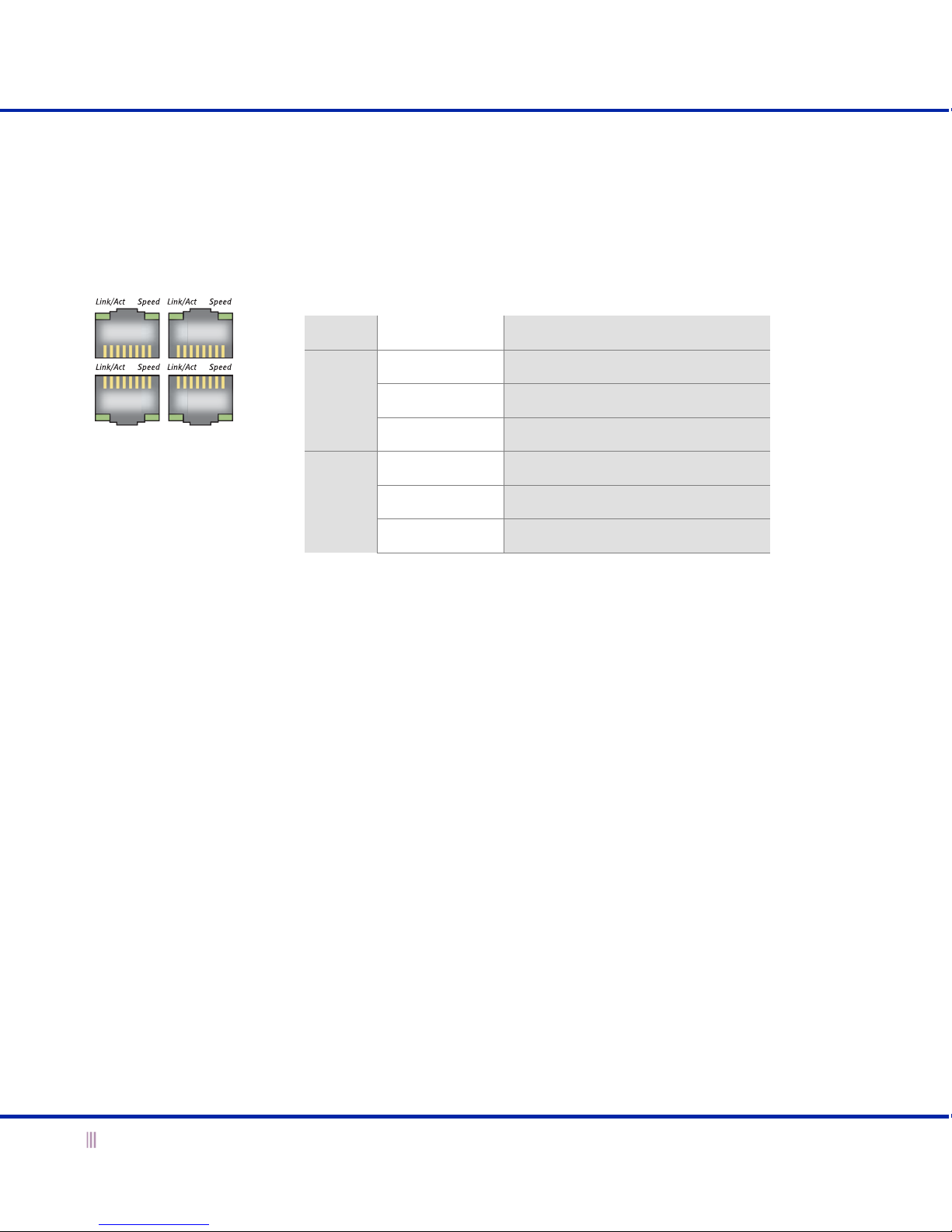
To see the link activity and connection speed of an Ethernet port, you can look at its Link/Act and Speed LEDs.
Figure 3 shows the status the LEDs convey through their color and illumination (steady glow or blinking).
Figure 3 LEDs
Connector Pin Assignments
An Infoblox appliance has three types of ports on its front panel:
•USB port (reserved for future use)
•Male DB-9 console port
•RJ-45 10Base-T/100Base-T/1000Base-T auto-sensing gigabit Ethernet ports
The DB-9 and RJ-45 connector pin assignments are described in Figure 4. The DB-9 pin assignments follow the
EIA232 standard. To make a serial connection from your management system to the console port, you can use the
RJ-45 rollover cable and two female RJ-45-to-female DB-9 adapters that ship with the appliance, or a female DB-9-to-
female DB-9 null modem cable. The RJ-45 pin assignments follow IEEE 802.3 specifications. All Infoblox Ethernet
ports are auto-sensing and automatically adjust to standard straight-through and cross-over ethernet cables.
10Base-T Ethernet and 100Base-T fast Ethernet use the same two pairs of wires. The twisted pair of wires
connecting to pins 1 and 2 transmit data, and the twisted pair connecting to pins 3 and 6 receive data. For
1000Base-T connections, all four twisted-pair wires are used for bidirectional traffic.
Label Color Port Status
Link/
Act Steady Green Link is up but inactive
Blinking Green Link is up and active
Off Link is down
Speed Steady Amber 1000 Mbps
Steady Green 100 Mbps
Off 10 Mbps
SpeedLink/Act
SpeedLink/Act SpeedLink/Act
SpeedLink/Act
MGMT
LAN1
HA
LAN2

Hardware Components
For the Infoblox-1852-A Appliance 7
Figure 4 Connector Pin Assignments
21 345
6789
21346578
78653421
DB-9 Connector Pin Assignments
Pin 10Base-T
100Base-T
Signal
1000Base-T
Signal
T568A
Straight-Throug
h Wire Color
T568B
Straight-Throug
h Wire Color
1 Transmit + BI_DA+ White/Green White/Orange
2 Transmit - BI_DA- Green Orange
3 Receive + BI_DB+ White/Orange White/Green
4 (not used) BI_DC+ Blue Blue
5 (not used) BI_DC- White/Blue White/Blue
6 Receive - BI_DB- Orange Green
7 (not used) BI_DD+ White/Brown White/Brown
8 (not used) BI_DD- Brown Brown
Male DB-9 Console Port
RJ-45 Ethernet Ports
Pin Signal Direction
1 (not used)
2Receive Input
3Transmit Output
4DTEReady Output
5 Ground —
6 DCE Ready Input
7 RTS (Request to Send) Output
8 CTS (Clear to Send) Output
9 (not used)
(Looking into the console
port on an Infoblox
appliance)
RJ-45 Connector Pin Assignments
(Looking into RJ-45
ethernet ports on an
Infoblox appliance)
Legend: BI_D = bidirectional; A, B, C, D = wire pairings

Introduction
8 Infoblox Installation Guide
Rear Panel
Figure 5 shows the rear panel components on the Infoblox-1852-A appliance.
Figure 5 Infoblox-1852-A, Rear View
Table 2 Rear Panel Components
Component Description
Air Vent An air vent that allows warm air to flow out of the appliance. Do not obstruct.
Power LED An LED that glows green when the power supply has power. It glows red when the
power supply is not fully seated or has failed. It is off when the power supply has no
power.
On/Off Switch A power switch to turn the power supply on and off.
Fan A fan to help maintain optimum operating temperature. Do not obstruct.
Power Outlet An IEC C-14 chassis plug for connecting the appliance to a standard AC power source.
On/Off
Switch
Power LED
Air
Vent
Fan
Power
Outlet
Redundant Power Supplies
Note: The label with the model and serial numbers is on the underside of the Infoblox-1852-A.

System, Environmental, and Power Specifications
For the Infoblox-1852-A Appliance 9
System, Environmental, and Power Specifications
System specifications describe the physical characteristics of each appliance. Environmental specifications
describe the temperature and moisture limits it can withstand. Power specifications describe the electrical range
within which the appliance circuitry can operate.
System Specifications
•Form Factor: 1-U rack-mountable appliance
•Dimensions: 1.75” H x 17.4” W x 22” D (4.44 cms H x 44.19 cms W x 55.88 cms D)
•Weight: Approximately 25 pounds (11.33 kg)
•Ethernet Ports: MGMT, HA, LAN1, LAN2 – auto-sensing 10Base-T/100Base-T/1000Base-T
•Serial Port: DB-9 (9600/8n1, Xon/Xoff)
•LCD Panel: LCD (liquid crystal display) with input buttons
Environmental Specifications
•Operating Temperature: 32 to 95 degrees F (-0 to 35 degrees C)
•Storage Temperature: -40 to 122 degrees F (-40 to 50 degrees C)
•Relative Humidity: 5% to 95%, relative humidity (non-condensing)
Electrical Power Specifications
•Input Voltage
—U.S.: 100 – 240 VAC switchable, 47 – 63 HZ, redundant, dual input
—Europe: 208 – 265 VAC switchable, 47 – 63 HZ, redundant, dual input
•Output Power: 360 watts each

Introduction
10 Infoblox Installation Guide
•Power plug and cable specifications by region:
Region Plug Type Cable Type Max Power
Rating
Max Temperature
Rating
North
America
NEMA5-15P
3-prong male plug
VCTF 3C 18 AWG 7A, 125 V 75° C
Japan NEMA5-15P
3-prong male plug
VCFI 3G 12A, 125 V 60° C
Europe CEE7 standard VII
2-prong male plug
H05VV-F 6A, 250 V 70° C
United
Kingdom
LP-60L 3-prong male
plug with fuse
H05VV-F 10A, 250 V 70° C
China RVV 300/ 500 3C X
1.00mmSQ
IEC 320 C 13/
GB2099.1 G B1002
10A, 250V 70° C
Taiwan VCTF 3x1.25mm
70° C
IEC-60320-C13 (BME)/
BLACK-ICC
10A, 125V 70° C
Australia
New Zealand
RVV 300/500 3C X
1.00mmSQ
IEC 320 C13/
GB2099.1 GB1002
10A, 250V 70° C
India
South Africa
1.0/3 HO5VVF3
70° C
IEC-320 C-13/BS
546SABS
10A, 250V 70° C
Tabla de contenidos
Otros manuales de Enrutador de red de Infoblox
Manuales populares de Enrutador de red de otras marcas

NETGEAR
NETGEAR FS526T - Switch Manual de usuario

Korenix
Korenix JetNet 5710G Series Manual de usuario

Automated Logic
Automated Logic ZN551 Manual del propietario

Cisco
Cisco ASR 1000 Series Manual del operador

EnGenius
EnGenius ESR-9710 Manual de usuario

Cisco
Cisco 805 Series Instrucciones de funcionamiento y seguridad