Inaxsys IN-16POEGWM Manual de usuario

IN-16POEGWM
User Manual
16 Port Gigabit Ethernet + 4 Combo Gigabit SFP
PoE+Web Smart Switch

FCC Warning
This Equipment has been tested and found to comply with the limits for a Class-A
digital device, pursuant to Part 15 of the FCC rules. These limits are designed to
provide reasonable protection against harmful interference in a residential installation.
This equipment generates, uses, and can radiate radio frequency energy. It may
cause harmful interference to radio communications if the equipment is not installed
and used in accordance with the instructions. However, there is no guarantee that
interference will not occur in a particular installation. If this equipment does cause
harmful interference to radio or television reception, which can be determined by
turning the equipment off and on, the user is encouraged to try to correct the
interference by one or more of the following measures:
Reorient or relocate the receiving antenna.
Increase the separation between the equipment and receiver.
Connect the equipment into an outlet on a circuit different from that to which the
receiver is connected.
Consult the dealer or an experienced radio/TV technician for help.
CE Mark Warning
This is a Class-A product. In a domestic environment this product may cause radio
interference in which case the user may be required to take adequate measures.

I
Content
Content………………………………………………………………………………….I
Introduction……………………………………………………………………………..1
Product Overview……………………………………………………………………………….1
General Feature…………………………………………………………………….1
L2 switching………………………………………………………………………………………..1
Quality of Service………………………………………………………………………………… 2
Security…………………………………………………………………………………………… .2
Specification……………………………………………………………………………………..3
Mechanical……………………………………………………………………………………....3
Package Contents……………………………………………………………………………...4
Hardware Description………………………………………………………………….5
Physical Dimensions / Weight………………………………………………………………...5
Front Panel……………………………………………………………………………………...5
LEDs Indicators…………………………………………………………………………………..5
Rear Panel………………………………………………………………………………………6
Hardware Installation…………………………………………………………………………..6
Software Description…………………………………………………………………..7
Login……………………………………………………………………………………………..7
Configuration……………………………………………………………………………………8
System ..…………………………………………………………………….…………….....8
Ports ………….…………………………………………………..…………………………..10
Vlan…………………………………….……………………….…………………………...11
Aggregation…………………………………………………………………………….….12
LACP……………………………………………………………………………….……….13
RSTP………………………………………………………………………………………..14
802.1x ………………………………………………………………………………………16
Snopping………………………………………………………………………….17
Mirrioring…………………………………………………………………………………18
QoS……………………………………………………………………………………….19
Filter..……………………………………………………………………………….…22
Power over Ethernet ………………………………………………………………………...23
Rate Limit…………………………………………………………………………………….24
Storm Control……………………………………………………………………………24
Monitoring…………………………………………………………………………………...26
Statistic Overview……………………………………………………………………… 26

II
Detailed Statistic………………………………………………………………………..26
LACP Status……………………………………………………………………………. 27
RSTP Status……………………………………………………………………………..28
IGMP Status……………………………………………………………………………..30
VeriPHY…………………………………………………………………………………..30
Ping……………………………………………………………………………………....31
Maintenance………………………………………………………………………………...34
Warm Restart…………………………………………………………………………....34
Factory Default………………………………………………………………………….34
Software Upload………………………………………………………………………..34
Configuration File Transfer…………………………………………………………....34
Logout……………………………………………………………………………………35

1
Introduction
Product Overview
This switch is a Web Management Switch equipped with 16-ports
10/100/1000BaseT(X) with 4-port gigabit SFP open slots. It was designed for
easy installation and high performance in an environment where traffic is on
the network and the number of users increases continuously. The compact
rigid desktop size was specifically designed for small to medium workgroups.
It can be installed where space is limited; moreover, it provides smooth
network migration and easy upgrade to network capacity.
In addition, the switch features comprehensive and useful function such as
QoS (Quality of Service), Spanning Tree, VLAN, Port Trunking, Bandwidth
Control, Port Security, SNMP/RMON, IGMP Snooping capability via the
intelligent software. It is suitable for both metro-LAN and office application.
General Features
- 16 Gigabit Ethernet ports with non-blocking wire-speed performance
- 16 tri-speed 10/100/1000 Mbps Gigabit Ethernet Media Access Controllers
(MACs)
- Eight tri-speed ( 10/100/1000 Mbps ) integrated copper transceivers
( PHY’s)
- Sixteen integrated SGMII ports
- Buffer Memory 500K Bytes
- 8,192 IP multicast groups supported
- Jumbo frame support at all speed ( 10/100/1000 Mbps) of up to 9.6K bytes
- Wire-speed automatic learning and CPU-based learning configurable per
port
- Support up to 24 trunks with up to 16 ports in a trunk
Layer-2 Switching
- 16 Giga Ethernet ports with non-blocking wire-speed performance
- 8,192 MAC addresses with wire-speed automatic learning and
CPU-based learning configurable per port
- Rapid Spanning Tree Protocol support ( IEEE std 802.1w)

2
- Multiple Spanning Tree support ( IEEE std 802.1s )
- IGMP, GARP, GMRP, and GVRP support
Quality of Service
- Programmable multi-layer classifier with four QoS classes per port
- Strict priority or weighted round-robin forwarding with guaranteed
bandwidth allocation
- Traffic class assignment based on port
- DSCP ( IPv4 & IPv6) and 802.1p support
- DSCP remarking for both IPv4 & IPv6 packets
- Provide Bridge support with multiple VLAN tags ( Q-in Q)
- Broadcast and multicast storm control
- Full-duplex flow control ( IEEE 802.3x ) and half-duplex back pressure
- Traffic shaping and policing per port in sites
- Link aggregation support based on layer 2-4 information ( IEEE Std
802.3ad)
Security
- Port-based access control support
- 4,096 VLAN support
- VLAN awareness on a per port basis
- Independent and share VLAN learning
- VLAN Q-in Q support (VLAN stacking )
- Source IP filter per port to block unwanted access
- Extensive snooping : BPDU, GARP, ARP, IPMC, IGMP, TCP/UDP
- TCP/UDP filter for CPU copy/redirect, frame snooping and frame
eradication
- DHCP filter to block unwanted DHCP servers on a per-port basis
- Multiple ARP filters for detection of ARP intrusion scans
- Extensive storm control: broadcast, multicast, uni-cast, ICMP and CPU
( ARP, BPDU) traffic control
- Per port CPU based learning option
- CPU mirroring per port and per VLAN

3
Specifications
Standard
IEEE 802.3 10BaseT
IEEE 802.3u 100BaseTX
IEEE 802.ab 1000BaseT
IEEE 802.3z 1000BaseSX/LX
IEEE 802.3x Flow Control
IEEE 802.3 Auto Negotiation
IEEE 802.3 Auto-MDI/MDI-X
IEEE 802.1ad Provider Bridge ( Q in Q )
IEEE 802.1x Port-based Network Access Control
IEEE 802.1Q VLAN Tagging
IEEE 802.3ad Link Aggregation
IEEE 802.1d Spanning tree protocol
IEEE 802.1w Rapid Spanning tree protocol
IEEE 802.1p Class of service, Priority Protocols
IEEE 802.3af- 2003 Power over Ethernet
IEEE 802.3at - 2009 Power over Ethernet
Number of Port
16-port 10/100/1000BaseT(X) + 4 Gigabit SFP Open Slots
LEDs Indicator
Per Port: Link/ Act, 1000M
Per Unit: Power
Power Consumption: 260 Watts (Max)
Power Input: 100~240V/AC, 50~60HZ
Product Dimensions/ Weight
45 × 440 × 330 mm (H × W ×D) / 4.4kg
4
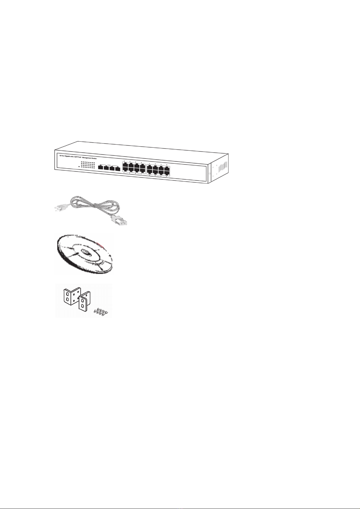
Package Contents
Before you start to install this switch, please verify your package that
contains the following items:
One Switch
One Power Cord
User Manual CD
One pair Rack-mount kit + 8 Screws

5
Hardware Description
This part primarily presents hardware of the web-smart switch, physical
dimensions and functional overview would be described.
Physical Dimensions/ Weight
45 × 440 × 330 mm (H × W × D) / 4.4KG
Front Panel
The front Panel of the web-smart Switch consists of 16 gigabit RJ-45 ports + 4
gigabit SFP open slot. The LED Indicators are also located on the front panel.
LED Indicators
The LED Indicators present real-time information of systematic operation
status. This table provides description of LED status and the meaning.
Table 1-1 LED Indicators
LED Status Description
Power
On Power on
Off Disconnect to Power Source
Blink Reset button for 3 seconds
Link/ ACT
On Link
Flashing Data activating
Off No device is attached
PoE On Port is linked to Power Device
Off No Power Device is connected
Note: The SFP ports are shared with normal RJ-45 ports 1,2,3 and 4. The
RJ-45 can not be used when SFP port link up.
LED Display RJ-45 Port
SFP ports for
optical transceivers

6
Rear Panel
The 3-pronged power plug is placed at the rear panel of the switch right side
shown as below.
Hardware Installation
Set the switch on a large flat space with a power socket close by. The flat
space should be clean, smooth, level and sturdy. Make sure there is enough
clearance around the switch to allow attachment of cables, power cord and
allow air circulation. The last, use twisted pair cable to connect this switch to
your PC then user could start to operate the switch.
Tabla de contenidos
Otros manuales de Cambiar de Inaxsys


