IDEA
TEC S.A. - Z.I. de Noville-les-Bois - rue Léopold Génicot 19A
- 5380 Fernelmont, Belgium - T
el: +32(0)81 42 00 10 - E-mail:
[email protected]User Guide PPS-TWIN V1.0 - Module V1.7
1.
Page 2
Safety and precautions
The safety of future users of this product depends on your installation. Therefore, it is critical that you read, understand, and follow all
instructions contained in this installation guide.
Some instructions and precautions that must be applied are listed below (see page 3 too) :
ITo install this equipment correctly, it is essential to have the understanding and the technical skills for the installation of automobile electronics.
IPlace this installation guide in a safe place and refer to it when necessary and for each installation. This manual must be delivered to the end
user.
IBefore wiring, disconnect the cable from the negative battery terminal. Failure to do so may result in electric shock or injury due to electrical
shorts. Connect again the cable on the negative battery terminal once the installation is completely finished.
IUse only in cars with a +12 or +24 volt negative ground (check with your car manufacturer if you are not sure). Failure to do so may result in fire,
etc.
IThe IDEATEC system must be powered by a DC voltage between + 10V and +30V. Use of AC voltage or DC voltage greater than + 30V can
result in property damage, fire hazard, serious injury or fatal injury to yourself and / or others.
INever install any devices or accessories inside the airbag deployment area. Such installation might reduce the effectiveness of the airbag or
prevent it from being deployed. It can also potentially damage or dislodge the device, causing serious or fatal injuries.
IInstallation of the equipment must comply with local and national electrical codes.
IIt is imperative to dimension correctly all wires installed and connected to the positive battery terminal (see the chart on page 3) and protected by
a proper fuse placed as close as possible to the battery.
ITo ensure a correct operation of the device installed, it is necessary to make a perfect connection to the negative terminal. The negative output of
the device must be connected to the negative terminal of the battery as directly as possible. The same applies to any elements controlled by the
installed device.
IDo not allow cables to become entangled in surrounding objects. Arrange wiring and cables in compliance with the manual to prevent obstructions
when driving. Cables or wiring that obstruct or hang up on places such as the steering wheel, shift lever, brake pedals, etc. can be extremely
hazardous.
IPosition the cables in such a way that they can never be damaged by vehicle vibrations or by impact (metal edge in direct proximity, mechanical
stress on the cable, etc.). Also make sure that all users of the vehicle can never damage the cables directly or indirectly.
IMake sure that none of the vehicle's original controls are affected by the installed device.
IIf you need to drill a hole in the dashboard, make sure that both sides are completely free to avoid damaging the vehicle.
IAlways install the console or the central unit in a ventilated area, and never close to a heat source. This area must also be protected against dust
and moisture.
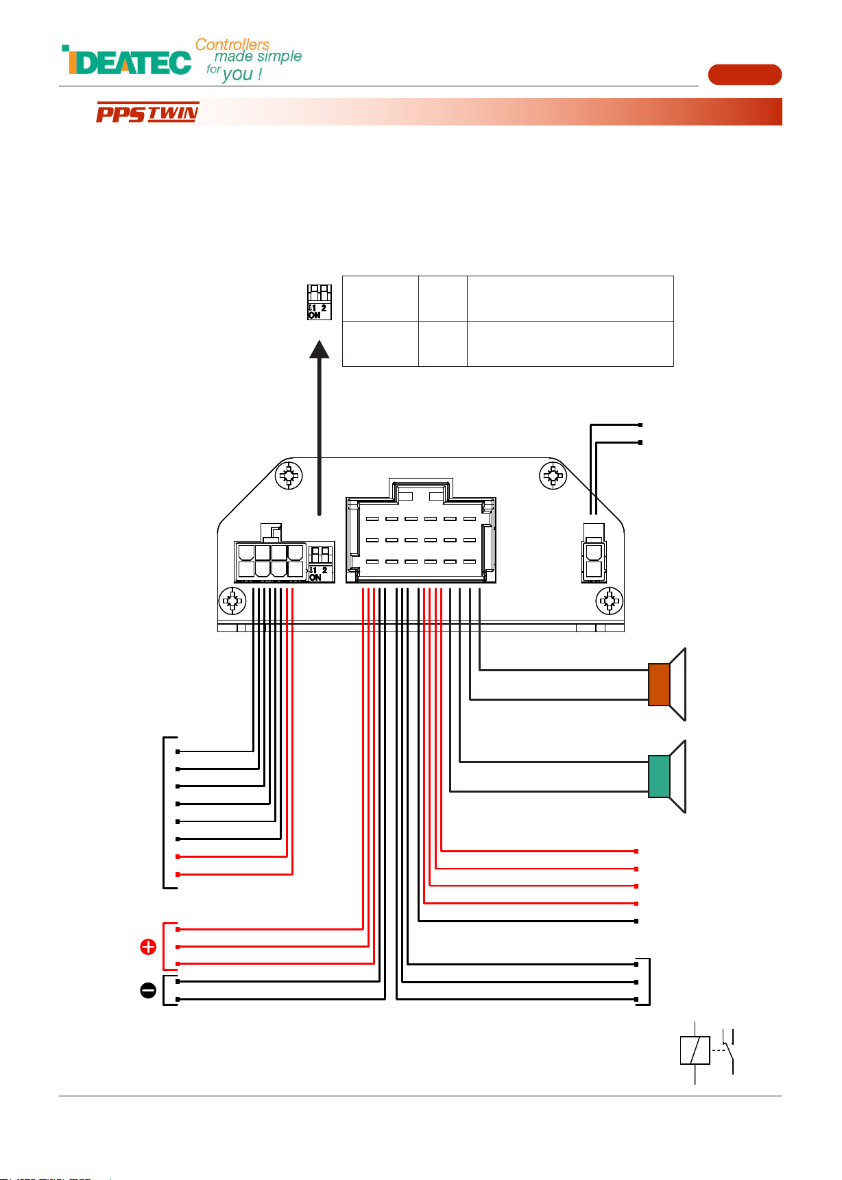
IPlease remind, any use of a relay connected to an output of the PPS-TWIN (positive or negative) must respect the usual precautions, namely the
installation of a freewheeling diode at least. Be careful to respect the polarity of the diode when connecting it.
In addition, if the current flowing through the relay contact is very high, opening the contact can cause sparks inside the relay and cause
disturbances in the wire harness. It is recommended in this case to add a capacitor absorbing the effects of sparks. Be careful to respect the
polarity of the capacitor when connecting it (see the diagram below). The capacitor must be able to support a minimum voltage of 50V.
IIf you have problems, do not attempt to repair the unit yourself. Return it to your IDEATEC dealer for servicing.
+
POSITIVE OUTPUT
RELAY
FREEWHEELING
DIODE
RELAY
FREEWHEELING
DIODE
NEGATIVE OUTPUT
OR
POSITIVE OUTPUT
RELAY
FREEWHEELING
DIODE
+
+
-
LOAD