Hyundai H-CCR8098 Manual de usuario
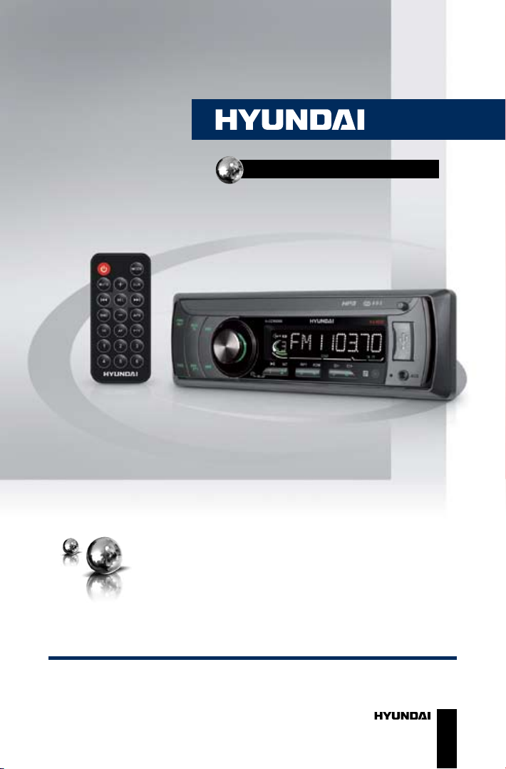
USB/SD/MMC-МЕДИАПЛЕЕР
USB/SD/MMC
MEDIA PLAYER
Руководство по эксплуатации Instruction manual
H-CCR8098

Contents
2
Dear customer!
Thank you for purchasing our product. For safety, it is strongly
recommended to read this manual carefully before connecting, operating
and/or adjusting the product and keep the manual for reference in the
future.
12
12
12
12
12
13
13
13
14
14
14
14
14
14
15
15
15
15
15
16
16
16
16
17
Table of contents
Before you start
Utilization of the product
Important safeguards
Installation/Connection
Installation
General notes
1. DIN front-mount (Method A)
Trim frame installation
2. DIN rear-mount (Method B)
Dismantling the unit
Detachable control panel
Connection
Connection diagram
Using the ISO Connector
Operation
Control elements
Front panel
Inner panel
Remote controller
Changing the battery
LCD layout
General operations
Turning on/off
Mode selection
Volume control
Mute function
Loudness
Audio parameter setting
Preset EQ modes
Beep function
Clock
AUX in jack
Radio operations
Band select
2
3
3
3
4
4
4
4
4
4
5
5
6
6
6
8
8
8
8
9
9
10
10
10
10
11
11
11
11
11
11
11
11
12
12
Manual tuning/Automatic tuning
Storing and recalling stations
Mono/Stereo reception
RDS function
AF (Alternative Frequency)
TA (Traffic Announcement)
PTY (Program type)
Other parameter setting
USB/SD/MMC operations
Connecting a USB/memory card
Playback
Track select
Folder select
Fast forward/rewind
Pause
Intro playback
Repeat
Random
ID3-tags
General information
Troubleshooting guide
Cleaning the unit body
Accessories
Specification

Before you start
3
If you want to dispose this product, do not mix it with general household
waste. There is a separate collection system for used electronic products
in accordance with legislation that requires proper treatment, recovery
and recycling.
Please contact your local authorities for the correct method of disposal.
By doing so, you will ensure that your disposed product undergoes the
necessary treatment, recovery and recycling and thus prevent potential
negative effects on the environment and human health.
Utilization of the product
Important safeguards
• Read carefully through this
manual to familiarize yourself with this
high-quality sound system.
• The beginning of operation is
the moment of the unit installation.
Before use the device in winter it
is recommended to heat up the
passenger compartment during
20 seconds or to the operation
temperature.
• Use the unit with the temperature
that goes beyond the operation
temperature greatly decreases the
operation resource of the screen and
other components of device and can
result an outage.
• Disconnect the vehicle’s negative
battery terminal while mounting and
connecting the unit.
• When replacing the fuse, be sure
to use one with an identical amperage
rating. Using a fuse with a higher
amperage rating may cause serious
damage to the unit.
• Make sure that pins or other
foreign objects do not get inside the
unit; they may cause malfunctions,
or create safety hazards such as
electrical shock.
• Do not use the unit in places
where it can be exposed to water,
moisture and dust.
• Do not open covers and do not
repair yourself. Consult the dealer or
an experienced technician for help.
• Make sure you disconnect the
power supply and aerial if you will not
be using the system for a long period
or during a thunderstorm.
• Make sure you disconnect the
power supply if the system appears to
be working incorrectly, is making an
unusual sound, has a strange smell,
has smoke emitting from it or liquids
have got inside it. Have a qualified
technician check the system.
• The unit is designed for negative
terminal of the battery, which is
connected to the vehicle metal. Please
confirm it before installation.
• Do not allow the speaker wires
to be shorted together when the
unit is switched on. Otherwise it
may overload or burn out the power
amplifier.

Installation/Connection
4
Installation
General notes
• Choose the mounting location
where the unit will not interfere with
the normal driving function of the
driver.
• Before finally installing the unit,
connect the wiring and make sure that
the unit works properly.
• Consult with your nearest dealer
if installation requires the drilling of
holes or other modifications of the
vehicle.
• Install the unit where it does not
get in the driver’s way and cannot
injure the passenger if there is a
sudden stop, like an emergency stop.
• Avoid installing the unit where it
would be subject to high temperature,
such as from direct sunlight, or from
hot air, from the heater, or where
it would be subject to dust, dirt or
excessive vibration.
DIN front-mount (Method A)
1. Install the sleeve into the
dashboard; ensure it is installed with
the correct side and there are no
obstacles (wires, dashboard elements,
etc) for the unit installation.
2. After installing the sleeve into the
dashboard, bend tabs fitting to the
size of the dashboard to fix the sleeve
in place.
3. Make the necessary wire
connections. Ensure the connections
are correct.
4. Install the unit into the sleeve until
the side locks are fixed.
2
1
182
53
1. Dashboard
2. Sleeve tab to bend
Trim frame installation
To install the trim frame, press it
to the unit body and push it to fix it
in place. This should be done before
installing the front panel; otherwise you
are not able to install the trim frame.
DIN rear-mount (Method B)
For this method, use the screw
holes in the lateral sides of the unit.
Fix the unit with the help of the factory
radio mounting brackets.
1. Select a position in which the
screw holes of the brackets (3) are
aligned with the screw holes in the unit
body, and screw in two screws (2) in
each side.
2. Screw.
3. Factory radio mounting brackets.
4. Vehicle dashboard.
5. Lock (remove this part).

Installation/Connection
5
2
2
5
5
4
3
The outer trim frame and
mounting sleeve are not used for
method of installation.
Dismantling the unit
a – Trim frame
b – Frame uninstall direction
c – Release key insertion
c
b
a
1. Switch off the unit and detach the
front panel.
2. Insert your fingers into the groove
in the front side of the trim frame
(apply some effort to detach the
frame). Pull the frame to detach it.
3. Insert the supplied release keys
into the both sides of the unit body
to click, as shown in the picture. To
extract the unit from the dashboard,
pull the release keys or the unit body
to pull it out.
Detachable control panel
Install the fastening hole on the
right side of the front panel on the
right fastening of the unit. Then insert
the left fastening on the panel into
the fixing hole on the left part of the
unit. Press on the upper right part of
the panel until a click. Ensure that the
panel is properly fixed, otherwise error
symbols may be displayed and some
buttons may not function.
To detach the front panel, press
OPEN button, then distract the left
side of the panel from the fastening of
the unit.
The control panel can easily
be damaged by shocks. After
removing it, place it in a protective
case and be careful not to drop it
or subject it to strong shocks. The
rear connector that connects the
main unit and the control panel is an
extremely important part. Be careful
not to damage it by pressing on it with
fingernails, pens, screwdrivers, etc.
If the control panel is dirty, wipe
off the dirt with soft, dry cloth only.
And use a cotton swab soaked in
isopropyl alcohol to clean the socket
on the back of the control panel.

Installation/Connection
6
Connection
Connection diagram
Fuse 5 A
RCA out right (red)
RCA out left (white)
Antena
jack
Using the ISO Connector
1. If your car is equipped with the
ISO connector, then connect the ISO
connectors as illustrated.
2. For connections without the ISO
connectors, check the wiring in the
vehicle carefully before connecting,
incorrect connection may cause
serious damage to this unit.
Cut the connector, connect the
colored leads of the power cord to the
car battery as shown in the color code
table below for speaker and power
cable connections.

Installation/Connection
7
Location Function
Connector A Connector B
1 - Rear right (+) - Blue
2 - Rear right (-) - Blue/White
3 - Front right (+) - Grey
4 Battery +12V/Yellow Front right (-) - Grey/White
5 Power antenna/Orange Front left (+) - Green
6 - Front left (-) - Green/White
7 Ignition/Red Rear left (+) - Brown
8 Ground/Black Rear left (-) - Brown/White
Power antenna wire is intended for power supply of the antenna and for
remote control of an additional amplifier.

Operation
8
Control elements
Front panel
1. PWR/MUT button
2. MOD/TA button
3. button
4. VOLUME knob/SELECT button
5. Display TA button
6. OPEN button
7. F/PS button
8. BND/PTY button
9. button
123 4 5 6
7 8 910 11 12 13 14 15 16 17 18
10. 1/ button
11. 2/INT button
12. 3/RPT button
13. 4/RDM button
14. 5/ - button
15. 6/ + button
16. IR port
17. AUX in jack
18. USB port
Inner panel
1 2 3
1. SD/MMC card slot
2. Connector
3. RESET button (hole)
Pressing RESET hole will erase
the clock setting and stored stations.

Operation
9
Remote controller (RC)
1
2
3
4
5
6
7
8
9
10
11
12
13
14
15
1. button
2. MUTE button
3. buttons
4. BND button
5. VOL- button
6. TA button
7. AF button
8. Number buttons
9. MODE button
10. VOL+ button
11. CLK button
12. buttons
13. SEL button
14. APS button
15. PTY button
Changing the battery
1. Press the catch and at the same
time pull out the battery tray.
2. Insert 1 lithium battery, type CR
2025 3 V with (+) mark facing up.
Insert the battery tray into the remote
control.
• Store the battery where children
cannot reach. If a child accidentally
swallows the battery, consult a doctor
immediately.
• Do not recharge, short,
disassemble or heat the battery or
dispose it in a fire.
• Do not expose or bring into
contact the battery with other metallic
materials. Doing this may cause the
battery to give off heat, crack or start
a fire.
• When throwing away or saving
the battery, wrap it in tape and
insulate; otherwise, the battery may
give off heat, crack or start a fire.
• Please direct the Remote
controller to the IR sensor of the front
panel.

Operation
10
LCD layout
1 2 3
4 5 6 7 8 9 10 11 12 13 14 15 16 17
1. Subwoofer indicator
2. Stereo signal reception indicator
3. Digit display (radio frequency, track
name/number, etc.)
4. Disc playback
5.,6. Various format playback
7. Video playback indicator (not
active)
8. Mute function indicator
9. Loudness function indicator
10. Intro playback indicator
11. Random playback indicator
12. Repeat playback indicator
13. EON function indicator
14. AF function indicator
15. TA function indicator
16. TP function indicator
17. PTY function indicator
General operations
Turning the unit on/off
Press PWR button on the panel or
button on the RC to turn the unit
on. Press and hold the button again to
turn the unit off.
Mode selection
Press MOD/TA button on the panel
or MODE button on the RC repeatedly
to select between Radio, auxiliary
input, USB or Memory Card modes.
Modes of operation are indicated
on the display. Memory card and
USB modes are not available unless
a memory card or USB device is
connected.
Volume control
Adjust volume by rotating VOLUME
knob or press VOL+/VOL- buttons on
the RC (00-42).
Mute function
Press MUT/PWR button on the
panel or MUTE button on the RC to
switch off the sound; press it again or
rotate VOLUME knob or press VOL+/
VOL- buttons on the RC to resume the
Tabla de contenidos
Idiomas:
Otros manuales de Reproductor multimedia de Hyundai

Hyundai
Hyundai H-DVB02T2 Manual de usuario

Hyundai
Hyundai H-CCR8104F Manual de usuario

Hyundai
Hyundai MPC 501 FM Manual de usuario

Hyundai
Hyundai TRC 191 DRSU3 Manual de usuario

Hyundai
Hyundai H-F4010 Manual de usuario

Hyundai
Hyundai H-DVB03T2 Manual de usuario

Hyundai
Hyundai DV2X 255 DVBT Manual de usuario

Hyundai
Hyundai H-CCR8100 Manual de usuario

Hyundai
Hyundai H-DVB01T2 Manual de usuario

Hyundai
Hyundai H-CCR8091 Manual de usuario


