Hot Shot 810-T Manual de usuario

Pg.
2HOW IT WORKS
3MOUNTING
3CODE SWITCH SETTINGS
3BATTERY BACKUP
3TRANSMITTER FUNCTION SWITCH SETTINGS
3INDICATOR LEDS
4TEST BEACON
4BASIC PIVOT INSTALLATION
5REINKE PIVOTS
6VALLEY 4000, 6000, AND PANELS WITH 3 SEC DELAY PCB.
7VALLEY 8000, PRO PANEL, SELECT PANEL AND SIMILAR
8T-L ELECTRIC PANEL
9ENGINE DRIVEN PIVOT AND T-L ENGINE PIVOT (ISUZU PANEL)
10 ZIMMATIC PIVOT 10 WIRE SYSTEM
11 ZIMMATIC PIVOT 11 WIRE SYSTEM
12 UNIT # SETTINGS
13 GROUNDING
Version : 160825
Hot Shot Systems Inc. will no longer sell or warranty its products for the use in controlling or monitoring pollu-
tants. However, the use of these controllers in non pollutant applications such as water tanks, water pumps, pivots,
irrigation systems and any other monitoring or control applications that do not involve pollutants are suitable for
these products.
IRRIGATION
810-T
TRANSMITTER GUIDE

2
CAUTION: Never connect any voltage to the HOT SHOT SENSOR Input terminals. The Hot Shot sup-
plies the voltage needed for sensor switching (use dry relay contacts only). Make sure the pivot’s well kill
terminals do not have voltage from previously wired configurations.
ATTENTION: Depending upon the style of system that your are going to control with the Hot Shot
Wireless Controller you may need to supply additional parts. Such as relays, step-down transformers, Mur-
phy switches etc. These items are suggested in the wiring guides that follow in this manual.
HOW IT WORKS
Think of the HOT SHOT system as a control wire going from the transmitter site to the receiver site. When the
Hot Shot Transmitter’s SENSOR ON-OFF Input is connected to COM, a small delay timer is started. After the
delay timer has expired, the transmitter will send the (Relay ON) command to the receiver. This will close the
relay contacts between N.O. and COM. When the SENSOR ON-OFF input at the transmitter is opened it will send
the (Relay OFF) command to the receiver switching the relay back to N.C. connected to COM. Battery backup in
the transmitter will still allow the HOT SHOT to work in case of power outage. Each system is coded with its own
four digit code so it will not interfere with other systems in the same area. The following manual has been pre-
pared to provide details for Transmitter installation on electric and engine driven pivots.
MOUNTING
Cabinets are a weatherproof UV protected NEMA 4X cabinet with mounting ears on top and bottom. The trans-
mitter/receiver control box can be mounted on the side of a control panel, pole or any other surface as long as the
antenna does not have metal running within 12” of the antenna whip. If longer range is needed, an external long
range antenna can be used. Do not mount the HOT SHOT receiver to the well engine or cover because the strong
vibrations can be harmful to the unit.
If installing these on a Variable Frequency Drive pump do not mount the receiver unit to the VFD because of the
potentially strong magnetic field interference that can be produced by these drives. The further away it is mounted
the better it is for the Hot Shot Unit.
BATTERY BACKUP
During a power outage, a gel cell rechargeable battery supplies power to the transmitter for approximately 24
hours. This allows the transmitter to send a shutdown signal to the receivers when the pivot has lost power. The
Hot Shot Transmitter comes with a battery save feature that will turn off the Hot Shot Transmitter if the voltage
drops from 12vdc to 10vdc. This function will add years of life to the gel cell battery.
Important... When the battery has discharged, it will take approximately 2 to 3 hours for the battery to
charge enough to operate the transmitter in case of another power failure. The battery should be replaced
every year for the best reliability during power outages.
ATTENTION: All Hot Shot units have a designated GROUND Terminal. Hot Shot units must have
there ground terminal connected to a proper ground or grounding system as per the NEC (National Electri-
cal Code) and or your local and state electrical code guidelines.

3
CODE SWITCH SETTINGS
All transmitters and receivers will be shipped from the factory with preprogrammed 4 digit system codes. This
ensures that your neighbor will not duplicate the same system code as your units. Your transmitter and receiver
system codes should already match, so you do not need to program any codes. If a new secure system code is
needed for your installation please call 785-623-1500 to be issued a secure system code for your area that the
system will be operating in.
If you ever need to replace a unit due to servicing, the field code can be programmed to match the existing or
new add on units. FOLLOW THE EXAMPLE BELOW…
FOR CODE QUESTIONS? CALL 785-623-1500
89
7
EXAMPLE: CODE 6789
KEY
7
8
9
0
5
63
4
6
OFF ON
Use the # KEY to the left
to make each digit of the
code. It takes three of the
switches to make one num-
ber of the code.
Use switches 1,2,3 for the
first # in the code. Switches
4,5,6 for the second #.
Switches 7,8,9 for the third
#. Switches 10,11,12 for the
fourth #.
Code Switches
INDICATOR LEDS
POWER Indicates that the Transmitter has power and is ready to operate.
TRANSMITTINGIndicates when the Transmitter is transmitting.
SENSOR LEDS When these LED’s are on it indicates that the terminal below it is connected to the COMMON terminal.
SENSOR LEDS
TRANSMITTER FUNCTION SWITCH SETTINGS
SWITCH#
4ON MAKES TRANSMITTER A UNIT #2 TRANSMITTER
4&5 both ON MAKES TRANSMITTER A UNIT #3 TRANSMITTER
5ON MAKES TRANSMITTER A UNIT #4 TRANSMITTER
5&6 both ON MAKES TRANSMITTER A UNIT #5 TRANSMITTER
6ON MAKES TRANSMITTER A UNIT #6 TRANSMITTER
(see more about this feature on page 12)
8ON ACTIVATES THE TEST BEACON (Used for testing and range finding only. When activated the transmitter will
send a code every 10sec cycling the receivers relay. To activate this feature put a jumper wire from the ON-OFF INPUT to
COMMON on the relay input you want to test. DO NOT have the receiver wired to the pump during this test. This func-
tion must be turned off for normal operation. (More details on page 4)
OFF NORMAL OPERATION MODE
9ON REFRESH (This function will retransmit the state of the Sensor Inputs once every 45 minutes.)
OFF NO REFRESH (Transmits the code only when there is a change of state on the Sensor Inputs.)
To watch a “How To” video on this feature click on the link below:
“CODE SWITCH SETTINGS”

4
BASIC PIVOT PANEL INSTALLATION
Most pivot installations will use this method because they only have a single throw relay in their panel. (Single
throw relays only have a COM and NO contact.) In most installations Function Switches 1 thru 8 need to all be
turned OFF. The pivots well control relay will be connected to the ON-OFF INPUT and the COMMON input
on the transmitter. When there is contact made between ON-OFF INPUT and COMMON (when requesting
water) the transmitter will send out the ON code to the receiver. When contact is opened between ON-OFF
INPUT and COMMON (such as when the pivot is finished or stop water) the transmitter will send out the OFF
code. See the diagrams below. Brand specific instructions are shown later in the wiring diagrams.
OPERATING THE TEST BEACON
The Test Beacon function is turned on and off by using FUCNTION SWITCH #8 (see above). This feature is
used for testing and range finding purposes only. To activate the Test Beacon first turn OFF the power to the
transmitter. Turn function switch #8 on and connect a small jumper wire from the ON-OFF INPUT terminal to the
COMMON terminal and then turn the power back ON to the transmit-
ter. See diagram below. When turned ON the Transmitting LED will
blink and the code will be transmitted every 10 seconds cycling the
receiver’s relay. DO NOT have the receiver relay wired up to the
pump during this procedure because it will continually open the relay
for 10 seconds and then close the relay for 10 seconds causing damage
to the pump.
Function switch #8 must be turned OFF, the jumper wire removed
and then turn off the power on the transmitter power switch to
take it out of Beacon Mode.
Trans Terminal Strip
Shown in the diagrams below is a generic diagram of how to wire a pivot panel to the Hot Shot Transmitter.
This method is used for one pivot with one well or one pivot with multiple wells that will always operate at
the same time. It can also be used with multiple pivots sharing one well or multiple wells as long as only 1
pivot is operating at a time and the other transmitters are switched OFF. The wiring for each transmitter is
the same.
WELL
1
FIELD LAYOUT
EXAMPLE 2
Pivot A and all the
wells will be on the
same field code.
WELL
1
WELL
2
PIVOT
A
WELL
3
PIVOT
A
FIELD LAYOUT
EXAMPLE 1
Pivot A and the well
will be on the same
field code.
Transmitter Terminal Strip
120v
120v neutral
PIVOT PANEL TERMINAL STRIP
PUMP
CONTROL
NO
PUMP
CONTROL
COM
This is the basic way
to wire up the Hot
Shot transmitter to
most pivot panels.
WARNING
Make sure there is no
voltage on the pump
control contacts.
Earth
Ground
To watch a “How To” video on this feature click on the link below:
“OPERATING THE TEST BEACON”
To watch a video on this click on the link below:
“UNDERSTANDING THE 810-T TRANSMITTER”

5
REINKE PIVOTS
WIRING INSTRUCTIONS FOR BASIC OPERATION
Typically all functions switches are off unless advanced features are needed. See function
switch setting on page 3 for details.
To supply the 120vac needed for the Hot Shot Transmitter to operate, run a wire from
the pivot panel’s J13 terminal to the 120vac Hot terminal on the transmitter. Run another wire
from the pivot panel’s neutral terminal J9 to the 120vac neutral terminal on the transmitter.
Make sure the pivot’s well kill terminals DO NOT have any voltage from previously
wired configurations. Run a wire from terminal J12 to the Hot Shot Transmitter’s COM input
terminal. Run a wire from terminal J11 to the Hot Shot Transmitter’s ON-OFF INPUT termi-
nal. Connect a wire from the Lighting Ground terminal of the Hot Shot Transmitter to an NEC
approved earth ground rod. See diagram below.

6
VALLEY MODELS
4000, 6000, & PANELS WITH 3 SEC DELAY PCB.
WIRING INSTRUCTIONS FOR BASIC OPERATION
Typically all functions switches are off unless advanced features are needed. See function
switch setting on page 3 for details.
To supply the 120vac needed for the Hot Shot Transmitter to operate run a wire from
the pivot panels 120vac hot terminal on the fuse block to the 120vac Hot input on the transmit-
ter. Run another wire from the pivot panels neutral buss bar to the second 120vac Neutral input
on the transmitter.
With these models we recommend that you use terminal #3 and #4 on the 3 Sec Delay
PCB to control the Sensor on the Hot Shot Transmitter. Remove the wires that currently go in-
to them and cap them off. Run a wire from terminal #3 on the 3 Sec Delay PCB to the COM
input on the transmitter. Run a wire from terminal #4 on the 3 Sec Delay PCB to the ON-OFF
input on the transmitter. Connect a wire from the Lighting Ground terminal of the Hot Shot to
an NEC approved ground rod. See diagram below.

7
VALLEY MODELS
8000, PRO PANEL, SELECT PANEL & SIMILAR
WIRING INSTRUCTIONS FOR BASIC OPERATION
Typically all functions switches are off unless advanced features are needed. See function
switch setting on page 3 for details.
To supply the 120vac needed for the Hot Shot Transmitter to operate run a wire from
the pivot panels terminal #3(120vac Hot) to the 120vac Hot terminal on the transmitter. Run
another wire from the pivot panels terminal #9 or #10 (120vac Neutral) to the 120vac Neutral
terminal on the transmitter.
To connect the pivot panels well control relay to the Hot Shot Transmitter run a wire
from terminal #15 (PUMP CONTROL NO) to the transmitters ON-OFF input terminal. Now
run a wire from terminal #16 (PUMP CONTROL COM) to the transmitters COM input termi-
nal. Connect a wire from the Lighting Ground terminal of the Hot Shot to an NEC approved
ground rod. See diagram below.
8
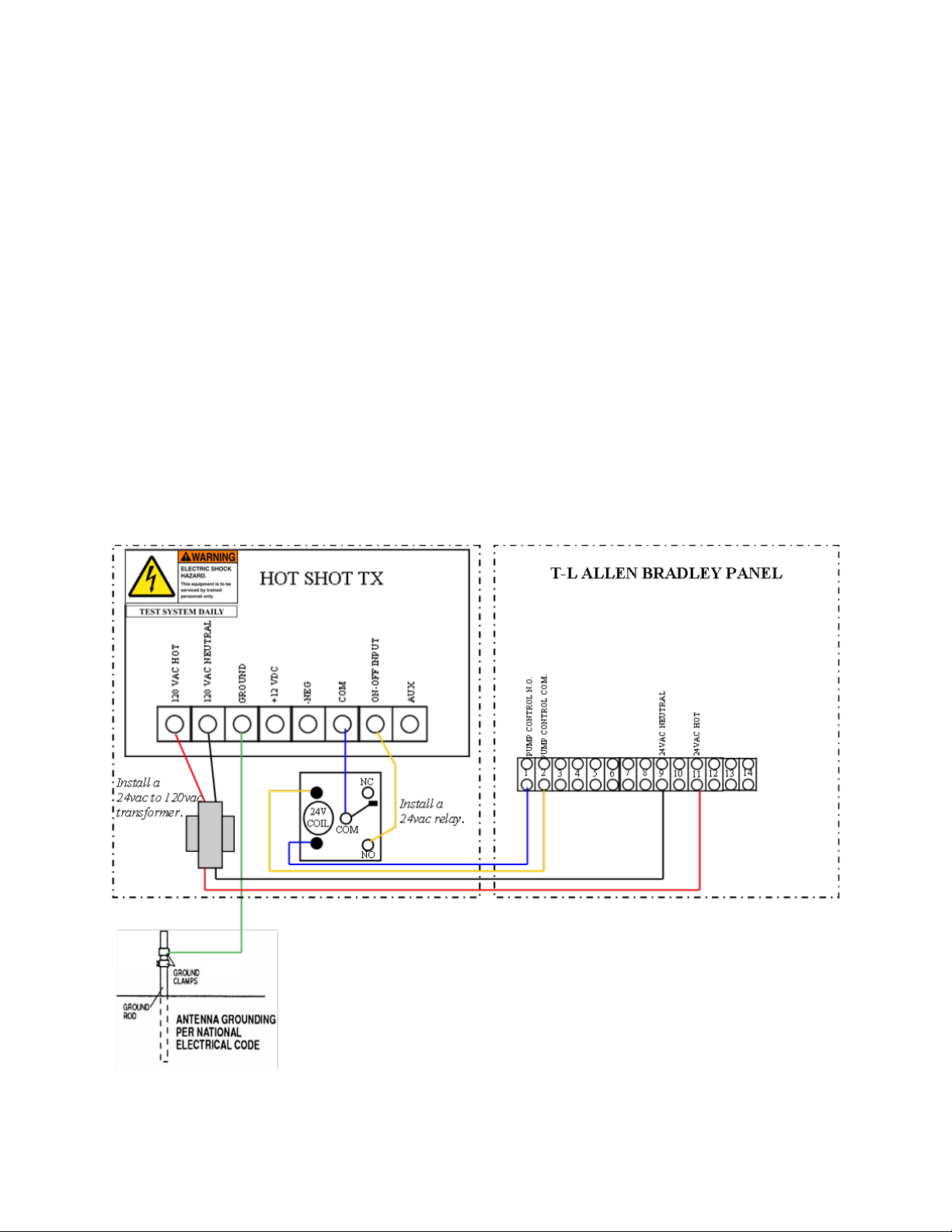
T-L ELECTRIC PANEL (ALLEN BRADLEY)
WIRING INSTRUCTIONS FOR BASIC OPERATION
Typically all functions switches are off unless advanced features are needed. See function
switch setting on page 3 for details.
Attention: This install requires a 24vac to 120vac transformer and a 24vac relay.
To supply the 120vac needed for the Hot Shot Transmitter to operate, install a 24VAC
to 120VAC step up transformer. These are available to purchase from Hot Shot Systems. Run
two wires from the 24 VAC input on the transformer to terminal #9 and #11 in the T-L Allen
Bradley Panel. Then take the 2 wires from the 120VAC output side and run them to the trans-
mitters two 120vac inputs. INSTALL a 24vac relay “Interface Relay” to control the Sensor
input on the transmitter. Control the Interface Relay by running a wire from the Allen Bradley
panel’s terminal #1 and #2 to each side of the Interface Relays coil terminals. Run a wire to
connect the COM terminal on the 24vac Interface Relay to the COM input on the transmitter.
Wire up the NO terminal on the 24vac Interface Relay to the ON-OFF Input on the Transmitter.
Connect a wire from the Lighting Ground terminal of the Hot Shot to an NEC approved ground
rod. See diagram below.

9
ENGINE DRIVEN PIVOTS
WIRING INSTRUCTIONS FOR BASIC OPERATION
Typically all functions switches are off unless advanced features are needed. See function
switch setting on page 3 for details.
Attention: This install requires a 12vdc relay.
Run a wire from the B terminal on the engines Murphy switch to the +12vdc input on
the transmitter. Run a wire from the ground on the Murphy or from the NEG of the engines
battery to the NEG input on the transmitter. Now install a 12vdc Interface Relay to control the
SENSOR inputs on the transmitter. To control the 12vdc Interface Relay run a wire from the
engines Murphy switch terminal C on a 117 or from the terminal NC on a 518 to one side of the
relays coil terminals. Run another wire from the ground on the Murphy or from the NEG of the
Hot Shot Transmitter to the other coil terminal on the 12vdc Interface Relay. Now run a wire
from the 12vdc Interface Relay’s NO terminal to the ON-OFF INPUT on the transmitter. Run
another wire from the 12vdc Interface Relay’s COM terminal to the COM input on the transmit-
ter. Connect a wire from the Lighting Ground terminal of the Hot Shot to the ground lug of the
panel. See diagrams below.

10
ZIMMATIC PIVOT 10 WIRE SYSTEM
WIRING INSTRUCTIONS FOR BASIC OPERATION
Typically all functions switches are off unless advanced features are needed. See function
switch setting on page 3 for details.
Attention: This install requires a 24vac relay.
To supply the 120v needed for the Hot Shot Transmitter to operate run a wire from the
pivot panels 120v X1 terminal to the 120vac Hot terminal on the transmitter. Run another wire
from the 120v X2 terminal to the 120vac Neutral terminal on the transmitter. INSTALL a
24vac relay “Interface Relay” to control the Sensor input on the transmitter. Control the Inter-
face Relay by running a wire from one side of the relay coil to terminal #64 and connect the
other side of the relay coil to terminal #4. Wire the N.O. side of the Interface Relay to the ON-
OFF INPUT terminal on the transmitter. Wire the COM terminal of the Interface Relay to the
COM terminal on the transmitter. Connect a wire from the Lighting Ground terminal of the Hot
Shot to an NEC approved ground rod. See diagram below.
Tabla de contenidos
Manuales populares de Transmisor de otras marcas


Dejero
Dejero EnGo 3x Manual de usuario

Rosemount
Rosemount 4600 Manual de usuario

Speaka Professional
Speaka Professional 2342740 Manual de usuario

trubomat
trubomat GAB 1000 Manual de usuario

Teledyne Analytical Instruments
Teledyne Analytical Instruments LXT-380 Manual de usuario

Rondish
Rondish UT-11 Manual de usuario


