Hofmann PMH-2 Manual de usuario

DIGITAL
pH / ORP / mV
CONTROLLER
PMH-2
USERS GUIDE
PMH-2 Instruction manual PAGE 1

TABLE OF CONTENTS
SPECIFICATIONS . . . . . . . . . . . . . . . . 3
INTRODUCTION . . . . . . . . . . . . . . . . . 5
Normal dosing (nor) 6
Normal Proportional dosing (no.P) 6
Adaptive proportional dosing. (Ad.P) 6
INSTALLATION . . . . . . . . . . . . . . . . . 9
Instrument . . . . . . . . . . . . . . . . . . . 9
Wiring of the PMH-2 10
Signal output 11
Electrodes 11
Starting up the Instrument. 11
CONFIGURATION . . . . . . . . . . . . . . . . 12
Looking at menus and values . . . . . . . . . 12
Default values for the PMH-2 instrument 13
Saving Values in Configuration. . . . . . . . . 14
OPERATION . . . . . . . . . . . . . . . . . . . 19
Initial check of the PMH-2. . . . . . . . . . . 19
Calibrating the PMH-2 with a simulator. . . . . 19
Selecting Mode of Operation. . . . . . . . . . 21
PMH-2 and Swimming Pools. . . . . . . . . . 27
WARRANTY . . . . . . . . . . . . . . . . . . . . 28
PAGE 2 PMH-2 Instruction manual

SPECIFICATIONS
Range: 0 - 14pH, 0.01 pH resolution
0 - 1999mV with 1mV resolution.
Display: 3 1/2 digit LCD displays.
Indicators: LED lights indicate set point operation, pulse, flow,
configuration and calibration status.
Calibration: All calibration parameters are programmed into non-
volatile memory.
Electrode: BNC, external of housing.
Temperature: Manual compensation selected in the configuration
menu if in pH mode. Temperature range from 0 to
100oC. Automatic compensation possible with a
TP-100 electrode connected.
Signal output: 4-20mA software configuration over range 0-14pH or
0-1000mV. Current output fully isolated. Maximum
termination impedance for 20mA is 1000 Ohms.
Control range: Set point range 0pH to 14pH or 0 to +1000mV
Pulsed output: Selected for Relay1 through setup program. Pulse
width adjusts automatically to suit dosing require-
ments. On time varies from continuous to minimum 1
second. Pulse interval increases / decreases to fur-
ther fine-tune a dosing cycle.
PMH-2 Instruction manual PAGE 3

Relay 1: 240 VAC, 5 Amps max. Resistive load. 3 terminals
provide earth, neutral and switched active. 5A fuse
protects instrument and relay output.
Relay 2 / Alarm: Potential free contacts.
Power: 240VAC 50Hz 7.5VA max. Hardwired with screw
terminals located under sub panel. 3 way terminal
providing 240VAC (A, N, E) located next to potential
free contacts allows for easy wiring of this terminal.
Housing: Fully sealed construction with hinged clear acrylic
front cover. IP55 specifications.
Dimensions: 166mm x 160mm x 105mm.
PAGE 4 PMH-2 Instruction manual
INTRODUCTION
The new PMH-2 controller features a simple and safe way for all
configuration and calibration procedures. All programmed parameters are
stored in non-volatile memory and are not lost if the instrument looses
power.
You use the ‘rotary encoder knob’ to scroll through setup menus and
dial up/down numbers when prompted to enter values for relay or alarm
setpoints, current signal low and high points etc.
The desired value is selected and saved by pushing the rotary encoder
knob. The rotary encoder only becomes active if invoked through the
instrument configuration program. This feature avoids setpoints or cali-
bration values being changed inadvertently.
The PMH-2 features 2 output relays. Relay1 has switched 240VAC.
This output can be configured for up/down dosing in on/off mode, propor-
tional dosing or adaptive proportional dosing. Relay2 has potential free
contacts with up/down dosing or configured as alarm.
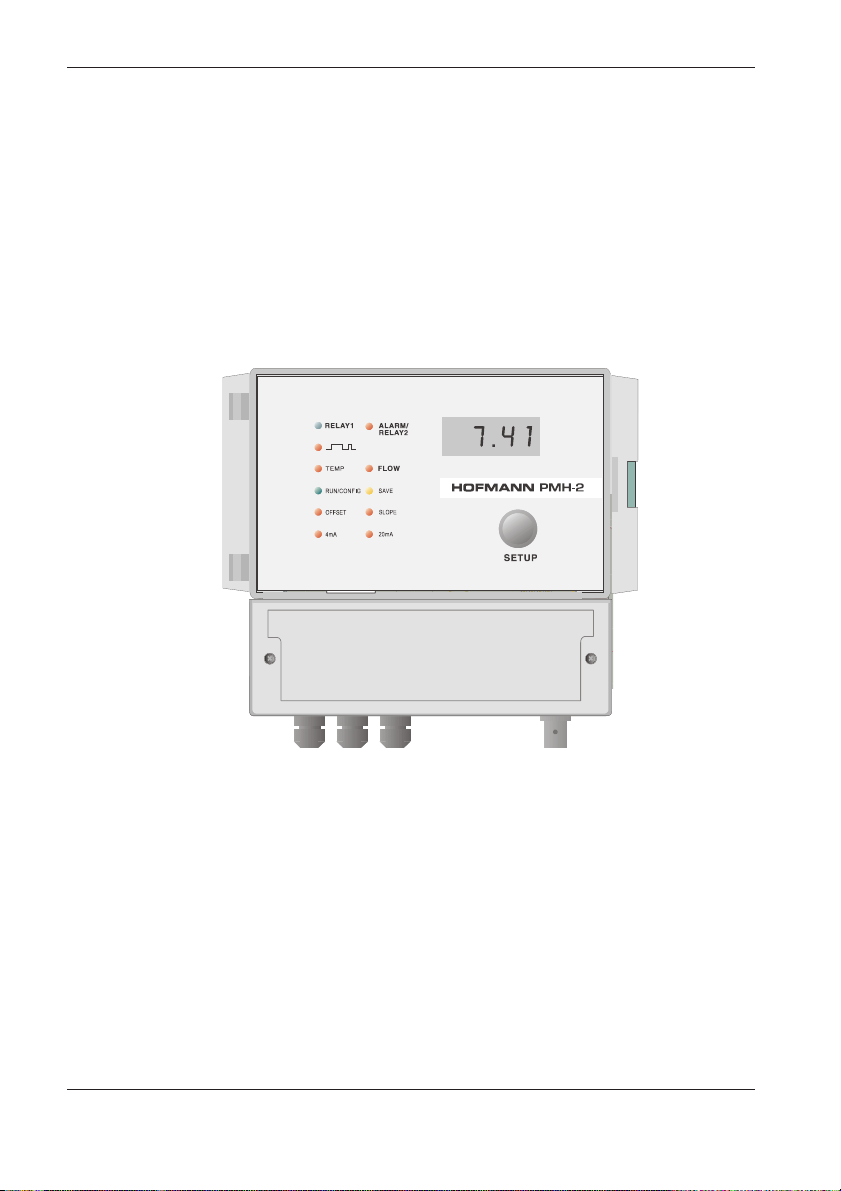
FIG 1 PMH-2 CONTROLLER
PMH-2 Instruction manual PAGE 5

LED’s show the operational status of the instrument or setup program
currently available. Pushing the encoder prepares for performing configu-
rations or calibrations. Rotating the encoder clockwise and pushing again
enters the configuration menu to set up the instrument. Rotating the
encoder anticlockwise and pushing enters the calibration menu. You scroll
through menus with the encoder knob and once a menu is selected values
are increased or decreased by rotating the encoder knob clock- or
anti-clockwise. The desired value is selected and saved with pushing the
encoder until the “SAVE” LED flashes two times. (See configuration)
The large LCD display shows either signal input, configuration or
calibration values such as set point or high/low alarm as selected by an
operator.
FThe rotary encoder only becomes active if invoked through the instrument
configuration program. This feature avoids setpoint or calibration values
being changed inadvertently.
Three modes of set point control are possible with Relay1:
Normal dosing (nor)
This is the normal dosing mode with simple on/off operation of the
output relay. Up or down dosing is possible with normal dosing.
Normal Proportional dosing (no.P)
The relay output starts to pulse with a shortening of the ON cycle and
a lengthening of the OFF cycle as the pH / mV moves toward the setpoint.
The behaviour of the pulse mode can be modified by setting a “gradient”
from 10 to 100. (See Fig. 6) Minimum default pulse ON time when reaching
the set point is 2 seconds. This can be changed from 1 to 9 seconds to
suit all applications. These configurations only becomes available if no.P
is selected. Up or down dosing is possible with normal proportional dosing.
Adaptive proportional dosing. (Ad.P)
The relay output of the PMH-2 instrument is controlled through a
complex algorithm that continuously monitors the difference between
actual pH / mV and set point. The output starts to pulse and varies the
PAGE 6 PMH-2 Instruction manual

ON/OFF cycle as the input value approaches the set point value. The
ON/OFF cycle however is also adjusted from a ‘correction factor’, which
in turn is governed by the history of a previous dosing cycle. This makes
for a fully dynamic dosing control, which adapts for widely varying dosing
conditions. (See Fig.7)
Dosing for an excessive period of time without a corresponding increase
in pH is recognized as a possible failure. The output begins to pulse,
preventing overdosing. The pulse output exhibits a very wide duty cycle.
The ON and OFF times are both dynamic, both varying from 1 to 60
seconds. Up or down dosing is possible with “Adaptive proportional
Dosing”. ! If using AdP the second relay must be configured as alarm !
FThe PMH-2 program prevents gross overdosing in the event of a process
upset or electrode failure. (Adaptive mode only)
FIG 2 LED's show different conditions.
PMH-2 Instruction manual PAGE 7

Temperature compensation (pH mode only) is set for 20oC by default.
This can be changed in the configuration program from 0 to 100oC.
A PT-100 temperature electrode connected to the terminals enables the
option for automatic compensation.
The PMH-2 features an alarm relay with potential free contacts. Low
and high alarm points are set in the configuration menu. ALARM/Relay2
can also be configured to perform as a second setpoint relay in either up
or down mode.
The flow switch input is configured to operate as N/O or N/C. (normally
open or normally closed) If no flow is detected relay 1 and relay 2 are
locked out and the relay’s LED flash. The flow LED indicates this condition.
The inherent accuracy and range configuration of the 4-20mA constant
current output together with full electrical isolation make it possible to
interface into a microprocessor, logic controller or data logger to further
expand the combination of installations with the PMH-2.
PAGE 8 PMH-2 Instruction manual

INSTALLATION
Instrument
Select a position for the controller to be mounted on a wall, not facing into
direct sunlight and protected from the weather elements as much as possible.
The PMH-2 should be installed near the treatment plant. Maximum length of
the co-axial cable used should not exceed 10 metres because of the very high
input impedance characteristic of a pH electrode.
The metal electrodes used for redox measurements are of much lower
resistance and longer coaxial cables can be used without any special
precautions.
Insert a round headed screw into the panel where the instrument is to
be attached. This screw determines the centre of the instrument location.
(Fig.3) Slide the instrument over the slot opening at the back, check that
the unit hangs level and secure it with two screws inserted through the
slots at the two bottom corners.
FDo not drill any holes into the enclosure to install the controller.
FIG 3 Attaching the DPH-4 to a wall
PMH-2 Instruction manual PAGE 9

Wiring of the PMH-2
It is imperative that all connections are wired through the cable gland
and the transparent lid is always tight to ensure that no corrosive liquids
inadvertently splash into the instrument.
The 3 terminals for relay1 provide an earth, neutral and switched
240VAC (active) . A metering pump, solenoid valve or other device
requiring 240V can be connected.
A suppression capacitor is already connected to filter electrical spikes
caused by switching solenoid valves.
The ALARM/relay2 terminal has potential free contacts. (N/O C N/C)
You need to determine the N/O or N/C of a flow switch when connecting
for proper configuration later on. Polarity does not matter when wiring a
flow switch.
FThe Set point relay terminals connect to earth, neutral and switched active
240V. (240VAC is supplied to these terminals when activated by the set point.)
FIG 4 Terminal layout for the PMH-2
PAGE 10 PMH-2 Instruction manual
Tabla de contenidos


