
HMS Networks Anybus X-gateway Manual de usuario
POWERLINK Slave
Anybus®X-gateway™Network Interface
USER MANUAL
SCM-1202-091 1.1 en-US ENGLISH

Important User Information
Disclaimer
The information in this document is for informational purposes only. Please inform HMS Industrial Networks of any
inaccuracies or omissions found in this document. HMS Industrial Networks disclaims any responsibility or liability
for any errors that may appear in this document.
HMS Industrial Networks reserves the right to modify its products in line with its policy of continuous product
development. The information in this document shall therefore not be construed as a commitment on the part of
HMS Industrial Networks and is subject to change without notice. HMS Industrial Networks makes no commitment
to update or keep current the information in this document.
The data, examples and illustrations found in this document are included for illustrative purposes and are only
intended to help improve understanding of the functionality and handling of the product. In view of the wide range
of possible applications of the product, and because of the many variables and requirements associated with any
particular implementation, HMS Industrial Networks cannot assume responsibility or liability for actual use based on
the data, examples or illustrations included in this document nor for any damages incurred during installation of the
product. Those responsible for the use of the product must acquire sufficient knowledge in order to ensure that the
product is used correctly in their specific application and that the application meets all performance and safety
requirements including any applicable laws, regulations, codes and standards. Further, HMS Industrial Networks will
under no circumstances assume liability or responsibility for any problems that may arise as a result from the use of
undocumented features or functional side effects found outside the documented scope of the product. The effects
caused by any direct or indirect use of such aspects of the product are undefined and may include e.g. compatibility
issues and stability issues.
Anybus®is a registered trademark of HMS Industrial Networks AB. All other trademarks mentioned in this document
are the property of their respective holders.
POWERLINK Slave Anybus®X-gateway™Network Interface User Manual SCM-1202-091 1.1 en-US

POWERLINK Slave Anybus®X-gateway™Network Interface User Manual SCM-1202-091 1.1 en-US
Table of Contents Page
1 Preface ................................................................................................................................. 3
1.1 About This Document .......................................................................................................3
1.2 Document history ............................................................................................................3
1.3 Document Conventions.....................................................................................................3
2 Description .......................................................................................................................... 4
2.1 Overview........................................................................................................................4
2.2 Data Flow .......................................................................................................................4
3 Installation........................................................................................................................... 5
3.1 Connectors .....................................................................................................................6
3.2 LED Indicators .................................................................................................................7
4 Configuration....................................................................................................................... 8
4.1 Anybus Configuration Manager ..........................................................................................8
A Technical Data ..................................................................................................................... 9

This page intentionally left blank

Preface 3 (10)
1 Preface
1.1 About This Document
This document describes how to configure the Anybus X-gateway POWERLINK Slave network
interface.
For additional documentation and software downloads, FAQs, troubleshooting guides and
technical support, please visit www.anybus.com/support.
1.2 Document history
Version Date Description
1.0 2018-02-06 First release
1.1 2019-04-11 Updated disclaimer
1.3 Document Conventions
Ordered lists are used for instructions that must be carried out in sequence:
1. First do this
2. Then do this
Unordered (bulleted) lists are used for:
• Itemized information
• Instructions that can be carried out in any order
...and for action-result type instructions:
►This action...
→ leads to this result
Bold typeface indicates interactive parts such as connectors and switches on the hardware, or
menus and buttons in a graphical user interface.
Monospaced text is used to indicate program code and other
kinds of data input/output such as configuration scripts.
This is a cross-reference within this document: Document Conventions, p. 3
This is an external link (URL): www.hms-networks.com
This is additional information which may facilitate installation and/or operation.
This instruction must be followed to avoid a risk of reduced functionality and/or damage
to the equipment, or to avoid a network security risk.
Caution
This instruction must be followed to avoid a risk of personal injury.
WARNING
This instruction must be followed to avoid a risk of death or serious injury.
POWERLINK Slave Anybus®X-gateway™Network Interface User Manual SCM-1202-091 1.1 en-US
Description 4 (10)
2 Description
2.1 Overview
POWERLINK is a deterministic real-time protocol for standard Ethernet. It is an open protocol
managed by the Ethernet POWERLINK Standardization Group (EPSG). POWERLINK extends
Ethernet according to the IEEE 802.3 standard with mechanisms to transfer data with predictable
delivery. The communication meets timing demands typical for high performance automation
and motion applications.
POWERLINK manages the network traffic using dedicated time-slots for isochronous and
asynchronous data. Only one networked device at the time gains access to the network media.
Thus transmission of data will never interfere and precise communication timing is guaranteed.
This mechanism is called Slot Communication Network Management (SCNM).
SCNM is managed by one particular networked device, the Managing Node (MN). All other
nodes are called Controlled Nodes (CN). The Anybus X-gateway POWERLINK Slave can participate
as a Controlled Node in POWERLINK networks.
2.2 Data Flow
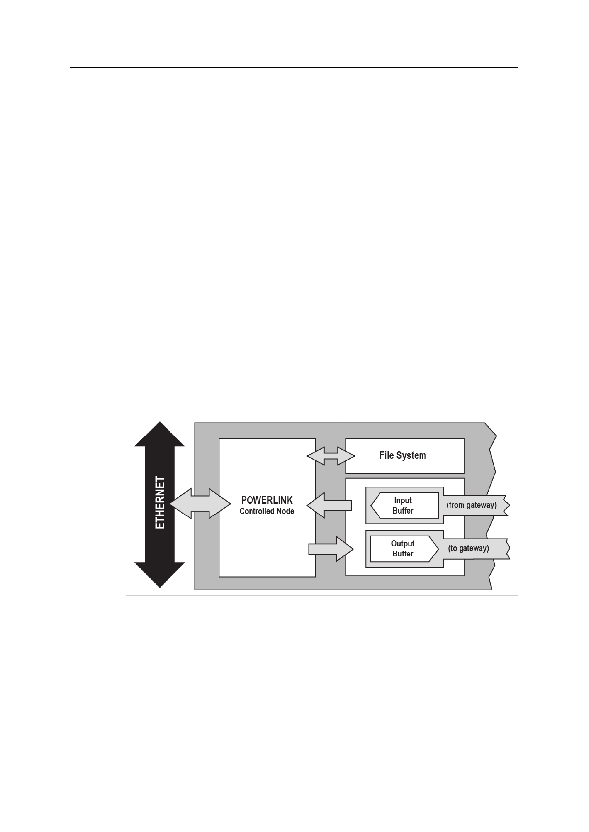
The Anybus X-gateway POWERLINK Slave network interface exchanges data via two memory
buffers that can be accessed via a built in webserver or over POWERLINK.
Input Buffer Contains data coming from the gateway, i.e. data from another network.
Output Buffer Contains data to be sent through the gateway to another network.
Fig. 1 Overview of data flow
POWERLINK Slave Anybus®X-gateway™Network Interface User Manual SCM-1202-091 1.1 en-US

Installation 5 (10)
3 Installation
This product contains parts that can be damaged by electrostatic discharge (ESD). Use
ESD prevention measures to avoid damage.
Make sure that you have all the necessary information about the capabilities and restrictions of
your local network environment before installation.
Prerequisites
The following items may be needed for installation:
• USB cable (included)
• Ethernet cable (not included)
• Configuration tool for POWERLINK (optional, not included)
• XDD file for POWERLINK (download from www.anybus.com/support)
• Anybus Configuration Manager (download from www.anybus.com/support)
Basic Installation Steps
1. Connect the POWERLINK Slave Interface to the network.
2. Connect the USB cable between the gateway and the computer to use for configuration.
3. Connect power and power on the gateway.
4. Download and install Anybus Configuration Manager
5. Download and Install the XDD file in the POWERLINK configuration tool.
6. Configure the gateway as required.
POWERLINK Slave Anybus®X-gateway™Network Interface User Manual SCM-1202-091 1.1 en-US
Installation 6 (10)
3.1 Connectors
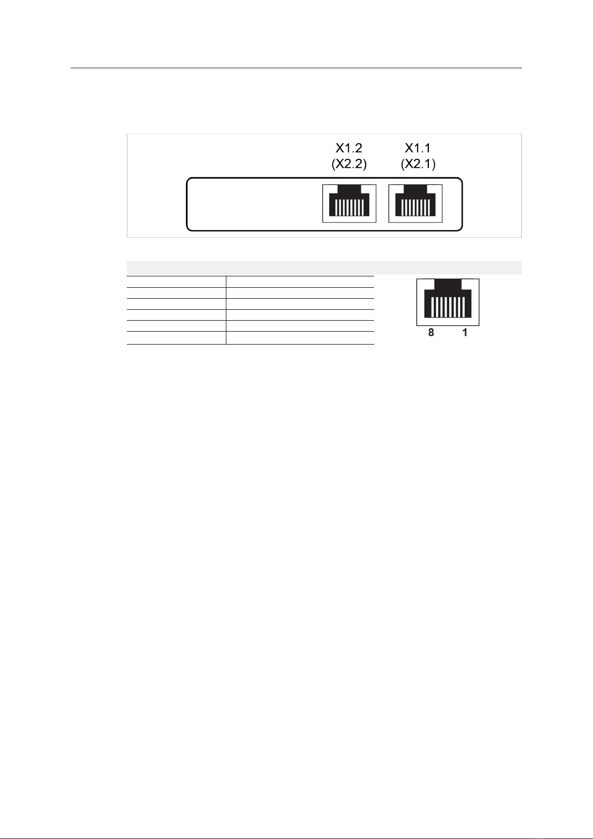
This interface has two RJ45 type Ethernet connectors that are labeled X1.1 /X1.2 when top-
mounted, and X2.1 /X2.2 when bottom-mounted.
Fig. 2 Network interface
RJ45 pin layout
Pin Function
1 TD+
2 TD-
3 RD+
6 RD-
4, 5, 7, 8 (reserved)
POWERLINK Slave Anybus®X-gateway™Network Interface User Manual SCM-1202-091 1.1 en-US
Installation 7 (10)
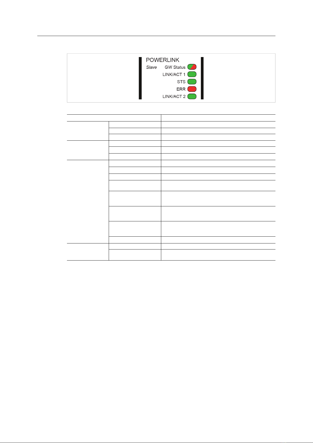
3.2 LED Indicators
Fig. 3 LED indicators
LED Indication Meaning
GW Status
Green Communication running
Red Communication error
Red, flashing Network interface error
LINK/ACT
Off No link
Green Link, no traffic
Green, flashing Link and traffic
STS
Off Not active or initializing
Green, fast flashing No POWERLINK traffic
Green, single flash Only asynchronous data.
Green, double flash Asynchronous and synchronous data
No PDO data
Green, triple flash Ready to operate
Asynchronous and synchronous data
No PDO data
Green Operating
Asynchronous and synchronous data
PDO data is sent and received
Green, slow flashing Stopped
Asynchronous and synchronous data
No PDO data
Red Error (see ERR LED below)
ERR
Off No error
Red STS LED also red = fatal error
STS LED not red = non-fatal error
POWERLINK Slave Anybus®X-gateway™Network Interface User Manual SCM-1202-091 1.1 en-US

Configuration 8 (10)
4 Configuration
4.1 Anybus Configuration Manager
Fig. 4 Anybus Configuration Manager
The interface can be configured over the USB port using Anybus Configuration Manager, which
can be downloaded from www.anybus.com/support.
The following settings are available when the POWERLINK interface is selected in Anybus
Configuration Manager:
Input PDO Size (bytes) Amount of cyclical I/O data to exchange on POWERLINK
Output PDO Size (bytes)
Input SDO Size (bytes) Amount of acyclical I/O data to exchange on POWERLINK
Output SDO Size (bytes)
Offline option Action if the POWERLINK network goes offline
Clear = reset the data from the network to zero (0).
Freeze = keep the current value.
Control word/Status word Enables/disables the control word and status word on POWERLINK.
Node ID (1–239) The Node ID of the POWERLINK interface.
Valid values = 1 to 239, 240 is reserved for the managing node.
For more information, see the built-in help in Anybus Configuration Manager.
POWERLINK Slave Anybus®X-gateway™Network Interface User Manual SCM-1202-091 1.1 en-US
Tabla de contenidos
Otros manuales de Tarjeta de red de HMS Networks

Manuales populares de Tarjeta de red de otras marcas


3Com
3Com EtherLink 3C509B Manual de usuario

TRENDnet
TRENDnet TEG-PCITX Manual de usuario

Cisco
Cisco MC16E Manual de usuario

Delta Electronics
Delta Electronics Braking Modules VFDB Series Manual de usuario

TwinMOS
TwinMOS Booming Manual de usuario

Dialogic
Dialogic Media Board DM/V1200BTEPEQ Manual de usuario

Buffalo
Buffalo AirStation WLI-PCM-L11GP Manual de usuario

National Instruments
National Instruments NI 9234 Manual de usuario

Hama
Hama 49276 Manual de usuario

Linksys
Linksys WCF54G - Wireless-G Compact Flash Card Manual de operación

Compaq
Compaq Wireless LAN 100 Manual de usuario

Bose
Bose PowerMatch Dante Manual de usuario