HEK MS 3000 Manual de usuario

USER'S MANUAL
MS 3000
MAST CLIMBING WORK PLATFORM
9095-032AIssue:02-2000
Thismanualis assigned to:

II MS 3000 • 9095-032A
©2000,HEK Manufacturing BV.,Middelbeers,The Netherlands
Nothingcontainedin this publicationmaybe copied, and/orpublishedby means of
printing,photocopying,microfilmorany other method without prior writtenpermissionfrom
HEKManufacturingB.V.

IIIMS 3000 • 9095-032A
HEK Manufacturing B.V.
Westelbeersedijk 18 P.O. box 2
5091 SM Middelbeers 5090 AA Middelbeers
The Netherlands The Netherlands
Tel : +31 13 51 48 653
Fax : +31 13 51 48 630

IV MS 3000 • 9095-032A

VMS 3000 • 9095-032A
FOREWORD
Read this instruction manual carefully before using the
mast climbing work platform. Take all the safety
precautions as described in chapter 3 into account.
FOREWORD
The mast climbing work platform is
provided with a rack and pinion drive.
The mast climbing work platform can be
quickly moved and is easy to transport.
The mast climbing work platform can be
freestanding or anchored.
The mast, which consists of separate
elements, can easily be adjusted in
height to match the height of the building
work. The mast is easy to assemble from
the platform.
The platform can be adjusted to the
shape of the façade.
The MS3000 mast climbing work platform
has a control system which makes it
possible to stop at any desired height.
Every care has been taken in the
construction of the mast climbing work
platform to ensure that all safety aspects
have been considered.
Depending on the application area, a
choice can be made from different
platform lengths, platform widths and
permissible loading.
This instruction manual describes only
the basic machine, in the standard form
supplied by HEK Manufacturing BV.

VI MS 3000 • 9095-032A
CONTENTS
CONTENTS
FOREWORD V
CONTENTS VI
SURVEYOFILLUSTRATIONS VII
ECDECLARATIONOFCONFORMITY VIII
MEANINGOF THESYMBOLSUSED IX
1. TECHNICALDETAILS 1-1
1.1 General 1-1
1.2 Electrical installation 1-5
1.3 Chassis 1-5
1.4 Platformconstruction,loading diagrams
andEMOSprogram numbers 1-6
1.4.1 Maximumloadingplatformconstruction 1-6
1.4.2 Maximumeccentrically loading
platformconstruction 1-6
1.5 Anchorforces 1-7
2. COMPONENTDESCRIPTION 2-1
2.1 Generaldescription 2-1
3. SAFETY 3-1
3.1 General 3-1
3.2 Safety prior to use 3-1
3.3 Safety in use 3-1
3.4 Safetyafteruse 3-3
3.5 Built-inandadditional safetyfeatures 3-3
4. TRANSPORT 4-1
4.1 Repositioning onthe building site 4-2
4.2 Repositioningwitha crane 4-3
5. CONTROLCOMPONENTS 5-1
5.1 Power supplysocket for theplatform 5-1
5.2 Platformcontrolbox 5-2
6. ASSEMBLY ANDANCHORING 6-1
6.1 Preparationforassembly 6-2
6.2 Groundsupport 6-3
6.3 Positioning the mast climbing
workplatform 6-4
6.3.1 Positioning the mast climbing
work platform 6-5
6.4 Assembly of the mast 6-7
6.5 Anchoring themast 6-10
6.6 Adjustingtheplatform width 6-12
6.7 Adjusting the EMOS system 6-14
6.8 Lightningprotection 6-14
7. OPERATION 7-1
7.1 General 7-1
7.2 Preparation 7-1
7.3 Testing 7-3
7.4 Brake test 7-3
7.5 Operationfromthe platform 7-4
7.6 Operationinan emergencysituation 7-4
8. DISASSEMBLYAND TRANSPORT 8-1
9. MAINTENANCE 9-1
9.1 General 9-1
9.2 Maintenanceintervals 9-1
9.3 Themotorbrake 9-3
9.3.1 Operation 9-3
9.3.2 Maintenance 9-4
10. MALFUNCTIONANALYSIS 10-1
11. MACHINEDISPOSAL 11-1
12. LISTOFKEYWORDS 12-1
APPENDICES 1

VIIMS 3000 • 9095-032A
CONTENTS
SURVEY OF ILLUSTRATIONS
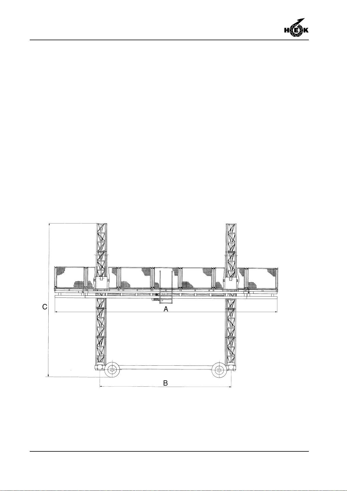
Fig.1 Dimensions X
Fig.1-1 Platform components 1-2
Fig.1-2 Mast element 1-2
Fig.1-3 Fence posts 1-2
Fig.1-4 Chassis 1-4
Fig.2-1 Basic set MS3000 2-1
Fig.4-1 Transport MS3000 4-1
Fig.4-2 Locking pin outrigger chassis 4-2
Fig.5-1 Platform power supply socket 5-1
Fig.5-2 Control box 5-2
Fig.6-1 Position machine 6-1
Fig.6-2 Ground support chassis 6-3
Fig.6-3 Distance to the facade 6-4
Fig.6-4 Locking pin outrigger chassis 6-5
Fig.6-5 Lower striker plate 6-5
Fig.6-6 Securing platform elements 6-5
Fig.6-7 Locking pin step 6-6
Fig.6-8 Securing platform posts and fences 6-6
Fig.6-9 Power supply socket 6-7
Fig.6-10 Main switch 6-8
Fig.6-11 Control buttons 6-8
Fig.6-12 Proximity switch 6-8
Fig.6-13 Mast element with mechanical
end stop 6-9
Fig.6-14 Mast cover 6-9
Fig.6-15 Anchor 6-11
Fig.6-16 Outrigger platform extension 6-13
Fig.6-17 Anchor ramp 6-13
Fig.6-18 Adjusting EMOS 6-14
Fig.6-19 Lightningprotection 6-14
Fig.7-1 Main switch 7-2
Fig.7-2 Emergencypush-button 7-2
Fig.7-3 Brake lever platform 7-3
Fig.7-4 Push-buttons control box 7-4
Fig.7-5 Brake lever platform 7-4
Fig.8-1 Brake lever platform 8-1
Fig.8-2 Locking pin outrigger 8-2
Fig.8-3 Locking pin outrigger chassis 8-2
Fig.9-1 Motorbrake 9-4
Fig.9-2 Motorbrake 9-5

VIII MS 3000 • 9095-032A
EC DECLARATION OF CONFORMITY
EC declaration of conformity for machines
(pursuantto AnnexIIaofthe MachineDirectives89/392/EEC)
We, HEKManufacturingbv
Westelbeersedijk 18
5091 SM Middelbeers
TheNetherlands
herebydeclarethat, on thebasisof its designandconstruction, the mastclimbingwork
platformnamedbelowandbrought into circulation byusconformtothe relevant basic
safetyandhealthrequirements contained in theECMachineDirectives.
Changesmadetothemachine without our consentinvalidatethisdeclaration.
Thisdeclarationapplies to themast climbing work platform:
HEK MS 3000
Inaccordancewith: ECMachineDirectives89/392/EG, Annex IV,
including91/368,93/44
ECnumber: 08/205/A 16-4912C, 06-01-1997
Certified by (‘Notified Body’): TÜV HANNOVER/SACHSENANHALT E.V.
HANNOVER,GERMANY
Date/Manufacturer’ssignature: Middelbeers,theNetherlands,
November1st 1999
Signatory: P.M. Blom, deputy manager

IXMS 3000 • 9095-032A
SYMBOLS
MEANING OF THE SYMBOLS USED
WARNING
Failing to (exactly) comply with
the working or operating
instructions may lead to serious
injury, fatal accident, severe
mechanical damage or
operating losses.
During use, no person may
stand under the machine.
Danger: High voltage.
Danger of falling objects.
XMS 3000 • 9095-032A
Fig.1 Dimensions
Tabla de contenidos
Otros manuales de Equipos de construcción de HEK


