
Haskel AA-8 Manual

OM-15J
www.haskel.com
Operating and Maintenance Instructions
取扱説明書
사용 및 정비설명서
操作和维护说明书
•Air Driven Air Amplifiers
Models: AA-8, AA-15 & AA-30
•空気駆動空気昇圧器
AA-8, AA-15, AA-30モデル
•에어 구동식 에어 증폭 펌프
모델: AA-8, AA-15, AA-30
•气动 空气增压器
号:AA-8, AA-15 和AA-30

Air Driven Air Amplifiers, AA-8, AA-15 & AA-30 • OM-15J
2
Introduction
This operation and maintenance manual has been prepared to assist in the installation, operation and
general maintenance of single acting single stage Haskel Air Amplifier models AA-8, AA-15 and AA-30.
They provide a means of boosting plant air or nitrogen gas to higher pressure at low flow.
Description
The drive is an automatic cycling reciprocating motor cycled by an unbalanced pilot operated spool valve.
The drive is directly connected to an integral pumping piston with inlet and outlet check valves. All three
models use the area ratio of the large drive piston vs. the small pump piston to boost inlet pressure. This
ratio is approximately indicated by the model number. Therefore, a model AA-8 can theoretically increase
its pump inlet pressure to 8 times the drive pressure, model AA-15 about 15 times, model AA-30 about 30
times.
Performance
Multiplying the model number x the air drive pressure simply estimates the approximate output pressure
at no flow (Stall). However, with output flow, output pressure will be lower as can be seen from the
individual model data in the catalog.
Compression Ratio vs. Efficiency vs. Service Life
Compression ratio is pump output vs. pump inlet pressure (psi absolute). Note: This is completely
unrelated to the “Area Ratio” discussed above.
Volumetric efficiency goes down in direct proportion to the compression ratio. It drops below 50% at about
12:1 compression. (e.g. Model AA-30 boosting to 2400 psia from 200 psia inlet). Therefore in continuous
duty applications, the pump output vs. pump inlet compression ratio should be as low as practical for best
service life.
Shop Air Moisture
A serious limitation to boosting typical shop air to high pressure is moisture concentration resulting in
short service life in the pump section. In general, if more than 600-800 psi output is needed dry nitrogen is
more practical. Consult catalog for more specific dryness level data.
Installation
All models may be mounted in any position. The exhaust muffler has been positioned at assembly to blow
cold air across the pump section. Do not change the position of the muffler.
Lubrication
It is not necessary or desirable to use an air line lubricator. Cycling valve spool and drive air barrel have
been pre-lubricated at the factory. Occasional relubricating of the spool o-rings (fig.2 #3.) is suggested
using P/N 50866 lubricant.
No lubricant of any kind is used in the pump section.

Air Driven Air Amplifiers, AA-8, AA-15 & AA-30 • OM-15J
3
Air Inlet System
Models AA-8-C, AA-15-C or AA-30-C include an air
inlet filter 1/2” NPT, regulator, gauge and speed
control valve all rated at 150 psi maximum.
These components are pre-plumbed per figure 1 to
provide unregulated inlet air from the drive inlet to the
pump section inlet.
Pump Section
If nitrogen is to be boosted, the pump inlet connecting
line from the air filter is removed. Nitrogen may then
be supplied directly to the pump inlet (not the drive
inlet) at up to 800 psi for model AA-8, 1500 psi for
model AA-15, 3000 psi for model AA-30. A particle filter at the pump inlet is recommended of suitable
working pressure such as Haskel model 28728.
Operation
The maximum outlet stall pressure can be limited by setting the drive regulator. However, operation with
less than 30 psi drive may result in unacceptably slow cycling. Consult distributor or factory on alternate
control for low drive pressures (16821 modification or air pilot switch).
Precise final pressure regulation is best accomplished from a high pressure regulator installed
downstream.
Pumping Speed
The pumping speed or cycling speed of the amplifier may be controlled by the speed control valve. This
valve is also an on-off valve to stop the amplifier yet allow inlet air or nitrogen to flow straight through the
pump section to outlet to equalize before start up.
Starting the Amplifier - (per schematic figure 1)
1. Speed control valve should be closed. (Handle at 90° to valve)
2. Allow inlet air or nitrogen to equalize pressure through the pump section and to fill the entire outlet
system.
3. Select the approximate stall pressure desired to be added to the equalized pressure. Divide by
approximately 8, 15 or 30 (depending on model). Set this amount on the gauge of the drive air
regulator. (For long range reliability, it should be no less than 30 psi.)
4. Open speed control valve and allow amplifier to pressurize outlet system. It should stall at
approximately regulated pressure times model number. (AA-8 will be approximately drive psi x 7 plus
inlet psi).
5. Readjust regulator if necessary. If more precise, constant control of output pressure is desired,
provide high pressure downstream regulator.

Air Driven Air Amplifiers, AA-8, AA-15 & AA-30 • OM-15J
4
Maintenance
(refer to individual assembly drawing and figure 2)
Air Valve Section
Remove spool or sleeve in the following manner:
1. Remove air exhaust muffler and fitting located in the lower end cap. Pull out spool; inspect 568017 o-
rings on spool and 568015 o-ring inside exhaust fitting. Relube; reinstall; retest before further
disassembly.
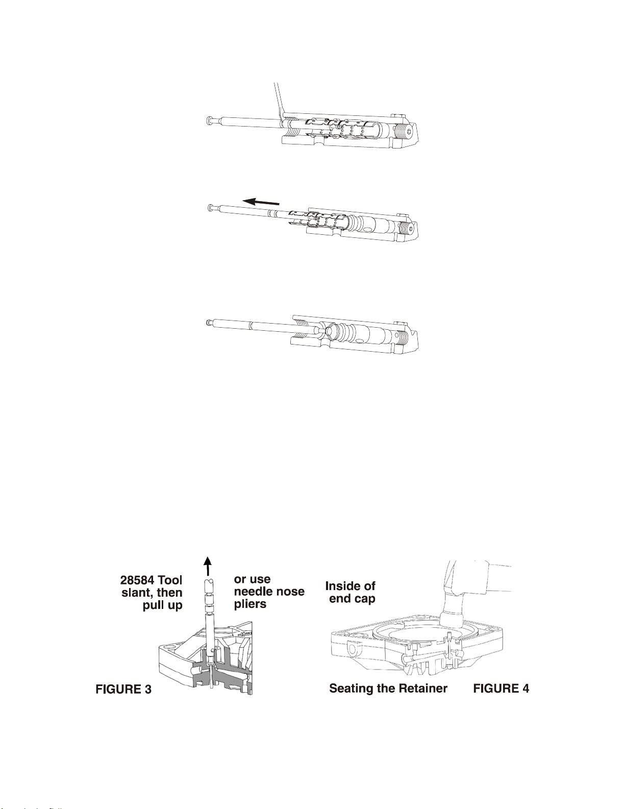
2. If necessary to remove sleeve and bumper (rubber faced spacer at inside end of sleeve) use tool P/N
28584 as shown-in photos 4 thru 6 or an L shaped hook bent from 1/8” diameter brass rod.
3. Replace any 568020 o-rings or the bumper - spacer if damaged, worn, or swollen.
4. Lubricate o-rings with light coat of Haskel 50866 lubricant.
5. Use lubricant liberally to hold bumper - spacer to sleeve with rubber side facing sleeve.
6. Push lubricated sleeve and bumper into end cap bore, all the way in one quick motion. (If bumper
drops off sleeve too soon, remove, regrease and repeat.)
7. Install spool.
8. Replace fitting and muffler.
FIGURE 2
1. 28584 Tool and end cap assembly (cutaway).
2. Insert tool or small hook in first row of holes in spool.
3. Pull straight out. Inspect o-rings. (Do not proceed with steps 4, 5, 6 unless required).
Air Driven Air Amplifiers, AA-8, AA-15 & AA-30 • OM-15J
5
4. Insert tool in second row of holes in sleeve and if necessary, pry out with screwdriver.
5. Pull straight out.
6. Insert bumper hook thru center bumper and pull straight out.
Pilot System
1. Remove hex o-ring sealed plug.
2. Remove spring and 27375 pilot stem (figure 3).
3. Inspect pilot stem and seat for foreign material. Replace stem if shank is bent or damaged.
4. Replace stem if molded seat is damaged.
5. Reassemble in the reverse manner.
NOTE: Unless excessive leakage occurs, it is not advisable to replace the o-ring seal for the shank of the
stem. This requires disassembly of the air section. If replacement is required, care must be taken in
installing the Tru-Arc retainer concentrically as shown in figure 4. Use the 27375 pilot stem valve as a
seating tool. Place the rubber valve face against the retainer and tap the top of the valve lightly with a
light hammer to evenly bend the legs of the retainer.

Air Driven Air Amplifiers, AA-8, AA-15 & AA-30 • OM-15J
6
Test procedure for pilot control valve:
After reassembly, if the pump will not cycle or “short cycles”, the following test procedure will determine
which of the pilot valves is faulty.
1. Remove the 17658-2 1/8” pipe plug in upper end cap.
2. Install 0-160 psi pressure gauge.
3. Apply air pressure to the air drive inlet. Gauge will read zero pressure if lower pilot valve has not
been actuated. Gauge will read full drive pressure if upper pilot valve has not been actuated. Correct
pilot valve action will cause gauge to immediately rise or fall from zero to drive pressure. A slow
increase in gauge reading indicates leakage in lower pilot valve or 568017 o-ring on inside end of
spool or 568020 o-ring on the inside end of the sleeve. A slow decrease in pressure indicates upper
valve or pilot tube end seals are faulty and repair is necessary. Check also for external air leaks at
plugs or worn 568015 o-ring inside exhaust fitting.
Disassembly and Repair of:
Air Drive Section and Air Piston
1. Remove (4) tie bolts. Then remove upper cap.
2. Remove air barrel and static seal o-rings.
3. Remove seal-on air piston.
Pump Section and Pump Piston
4. Remove high pressure end cap.
5. Remove, pin and nut on pump piston.
6. Refer to assembly drawing for further removal and reinstallation of piston parts. Do not use lubricants
of any type. These parts operate dry.
7. Inspect bore of high pressure barrel. Replace if worn or scratched.
8. Assemble all pump piston parts and tighten nut while confined within barrel bore.
Drive Reassembly
9. Inspect, replace and install all parts in air drive section per individual assembly drawing.
10. Relubricate air barrel with 50866 Haskel lubricant.
11. Alternately (cross-wise) torque air drive tie rods to a maximum torque of 16-18 ft-lbs.
Check Valves
Remove, clean, and inspect parts per individual assembly drawing. Replace any parts if damaged.

Air Driven Air Amplifiers, AA-8, AA-15 & AA-30 • OM-15J
7
Troubleshooting Guide
Symptom Cause Remedy
1. Will not run at low air
drive pressures (10 - 15
psi).
1. Excess friction of spool o-
rings 568017. 1. Necessitates relubrication or
replacement of spool o-rings. (See
instruction for removing spool in
Figure 2, steps 1, 2, 3.)
2. Pump will not cycle, or
slow cycling. 1. Leakage of flow and/or pilot
tubes.
2. Indication that one or both
pilot valves are
malfunctioning.
3. Build-up of residue in
muffler.
1. Replace o-rings on flow pilot tubes.
2. Remove pilot valves, inspect and
repair per instructions in maintenance
section.
3. Remove muffler, disassemble and
clean.
1. Small inlet air supply line.
Restriction not allowing
drive seals to function
properly.
1. Increase air inlet piping to 1/2”. Test.
Replace o-rings in the following order
(test each step):
a. No. 568015 o-ring inside hex
exhaust port fitting.
b. Spool o-rings No. 568017.
c. Sleeve o-rings No. 568020. (See
instructions for removing and
replacing o-rings.)
2. High pressure piston
leakage (AA-15, AA-30). 2. Shutoff drive air and remove muffler
and cycling spool completely. Apply
pressure to pump inlet only. If leakage
flow is audible out of spool cavity,
replace pump piston parts per
individual assembly drawing.
3. High pressure piston
leakage (AA-8). 3. Remove 3/8” O.D. tube at branch of
inlet tee. Plug branch of tee. Apply
inlet pressure to tee. If leakage flow is
audible out of 3/8” tube, replace pump
piston seal parts per individual
assembly drawing.
4. Check valves contaminated
or damaged. 4. Remove, inspect, clean or replace
check valve parts as necessary.
3. “False” or double cycling
or continuous exhaust
bleeding.
4. Unit will not dead head
(stall).
5. Insufficient pressure at
pump inlet. 5. See catalog for minimum pump inlet
pressures to maintain efficiency.
5. Excessive moisture or
liquid outside of muffler. 1. Air filter full of water. 1. Drain air filter.

空気駆動空気昇圧器 AA-8, AA-15 & AA-30 モデル • OM-15J
8
はじめに
この取扱保守説明書は単動単段ハスケル空気昇圧器AA-8、AA-15およびAA-
30モデルの設置、運転、および一般的な保守を助けるために作成されたものです。この装置はプラント
空気源または窒素ガスを低流量、高圧力に昇圧するものです。
解説
駆動部は、不平衡パイロット操作式スプール弁による、自動往復サイクル駆動装置です。駆動部は入口
と出口にピストンがついている複合型ポンプピストンに直接接続されます。3つのモデルとも、流入圧
力を昇圧するために、大きい駆動ピストンと小さいポンプピストンの面積比を利用しています。この面
積比の概略の値がモデル番号になっています。すなわち、AA-
8モデルは理論上ポンプの入り口圧力を駆動圧力の8倍に昇圧する事ができ、AA-
15モデルでは約15倍、AA-30モデルでは約30倍となります。
特性
モデル番号と駆動圧力の掛け算によって、流量ゼロの時(せき止め状態)の出口圧力が概算できます。
実際には出力流量により、カタログに示した各モデルのデータより出口圧力は低くなります。
圧縮比 vs. 効率 vs. 寿命
圧縮比はポンプの出口圧力対ポンプ入り口圧力(絶対圧)の比です。注意:この値は、上述の面積比と
は全く無関係です。
容積効率は圧縮比に反比例して下がります。容積効率は、約12:1の圧縮では50%より低くなります。(
例えばAA-30は入口圧力13.8bar absから出口圧力165.5 bar
absまで昇圧する。)しかしながら、連続負荷運転の場合、運転寿命のためには、ポンプ出口圧力対ポン
プ入口圧力の圧縮比は低い方がよいことになります。
設備空気の湿度
一般的な設備の圧縮空気を高圧空気に昇圧する場合、圧縮空気の湿度には重要な制限があります。これ
によって、ポンプ部の寿命が短くなることがあります。一般的に41.4 bar~55.2
barより高い出口圧力が必要な場合には、乾燥した窒素を使用するのが実用的です。特定の乾燥度のデー
タはカタログをご参照ください。
据付
各モデルとも、どのような位置にも据え付けることができます。排気マフラーは冷たい空気をポンプ部
に吹き付けるように、組立てられています。マフラーの位置を変えないようにしてください。
潤滑
圧縮空気系の循環は不要で、むしろ望ましくありません。サイクル弁のスプールと駆動空気バレルは工
場組立時にあらかじめ潤滑されています。時々、スプールOリング(図2の#3)に部品番号50866潤滑
剤を塗布してください。
ポンプ部にはいかなる種類の潤滑剤も使用しないでください。

空気駆動空気昇圧器 AA-8, AA-15 & AA-30 モデル • OM-15J
9
空気流入系
AA-8-C、AA-15-C、AA-30-Cの各モデルには、1/2B
(15A) NPT
空気入口フィルター、圧力調整弁、圧力計、および調
速弁が付属しています。各機器の最高使用圧力は10.3
bar です。
この各機器は図1に示したようにあらかじめ接続され
ており、圧力調整されていない入口空気が駆動部入口
からポンプ部入口へ供給されます。
ポンプの選択
窒素を昇圧する場合、空気フィルターからのポンプ流
入接続配管ははずします。そして、窒素はポンプ流入口(駆動ガス入口ではなく)に直接供給します。
供給圧力は AA-8 モデルでは55.17 bar 以内、
AA-15 モデルでは 103.4 bar 以内、AA-30 モデルでは 206.9 bar
以内としてください。ポンプ流入口にはハスケル 28728
モデルのような、適切な作動圧力の粒子フィルターの設置することをお勧めします。
操作
ポンプ流出口のせき止め状態の最高圧力は駆動用圧力調整弁によって制限することができます。但し、2
barに満たない駆動圧力による運転は、異常に低速の運転となることがあります。取扱店または工場に定
圧駆動の制御オプションについてご相談ください。(16821オプションまたは、空気パイロットスイッチ
)
精密最終圧力調整は流出口の下流に高圧調圧弁を使用する方法が最も効果的です。
流速
流速、すなわち昇圧器の運転速度は速度調整弁で調整できます。この弁は増幅器の機能を入り切りする
弁、さらに入口空気または窒素がポンプ部を通り抜けてそのまま流出口まで流れ、起動前に出口圧力を
入口圧力と均圧にする弁としても使用されます。
増幅器の始動 -(説明図1参照)
1. 速度調整弁は閉止しておきます。(ハンドルが弁に対し90°)
2. 入口空気圧力が増幅器を通して出口まで全体同圧になるようにします。
3. 全体を満たしている同圧に対して、付加したい概略の締め切り状態(最高)圧力を選定します。その
圧力を8、15、または30(モデルによる)で割り算します。圧力計を使用して駆動空気圧力調整弁を
この圧力に設定します。(安定運転のため、2 bar以上としてください。)
4. 速度調整弁を開けて昇圧器により出口側機器を加圧します。昇圧器は調整済み圧力かけるモデルの面
積比番号付近出口の圧力でせき止め状態になります。(AA-8は駆動圧力×7+流入圧力)
5. 必要に応じて圧力調整弁を再調整します。出口圧力をより正確に一定圧力に調整する必要があれば、
上記Bに示したように流出口圧力調整弁を設置してください。

空気駆動空気昇圧器 AA-8, AA-15 & AA-30 モデル • OM-15J
10
保守
(各組立図および説明図2をご参照ください。)
空気弁部
スプールあるいはスリーブを以下の要領で取り外してください。
1. 下部エンドキャップのところにある排気マフラーとフィッティングをはずします。スプールを引っ張
ってはずします。スプールについているOリング568017と排気フィッティングの内側についている
Oリング568015を点検します。次の作業に進むまえに再潤滑、組み立て、再試験を行なってくださ
い。
2. 必要に応じて、スリーブとバンパー(スリーブの内側の端についているゴムの表面のスペーサー)を
工具(部品番号28584)を使用して、写真4~6に示すようにはずします。L型のフックが3.2
mmの真鍮の棒についています。
3. Oリング568020またはバンパー/スペーサーが傷ついたり、減ったり、膨らんだりしていた場合、
交換してください。
4. Oリングにハスケル潤滑剤50866を薄く塗ってください。
5. 潤滑剤を十分使用してバンパー/スペーサーをスリーブにくっつけておくようにしてください。その
とき、ゴムの面がスリーブに当たる向きにつけてください。
6. 潤滑したスリーブとバンパーをエンドキャップのボアの中に一気に完全に押し込みます。(バンパー
がスリーブからすぐに落ちてしまった場合は、はずして、潤滑剤を塗りなおして、作業を繰り返して
ください。)
7. スプールを取り付けます。
8. フィッティングとマフラーをもとに戻します。
図2
1. 工具28584とエンドキャップユニット(断面)
2. 工具、あるいは小さいフックをスプールの中の最初の列の穴に差し込みます
Este manual sirve para los siguientes modelos
2
Tabla de contenidos
Idiomas:
Otros manuales de Amplificador de Haskel


