
Harbor Freight Tools 94861 Manual de usuario
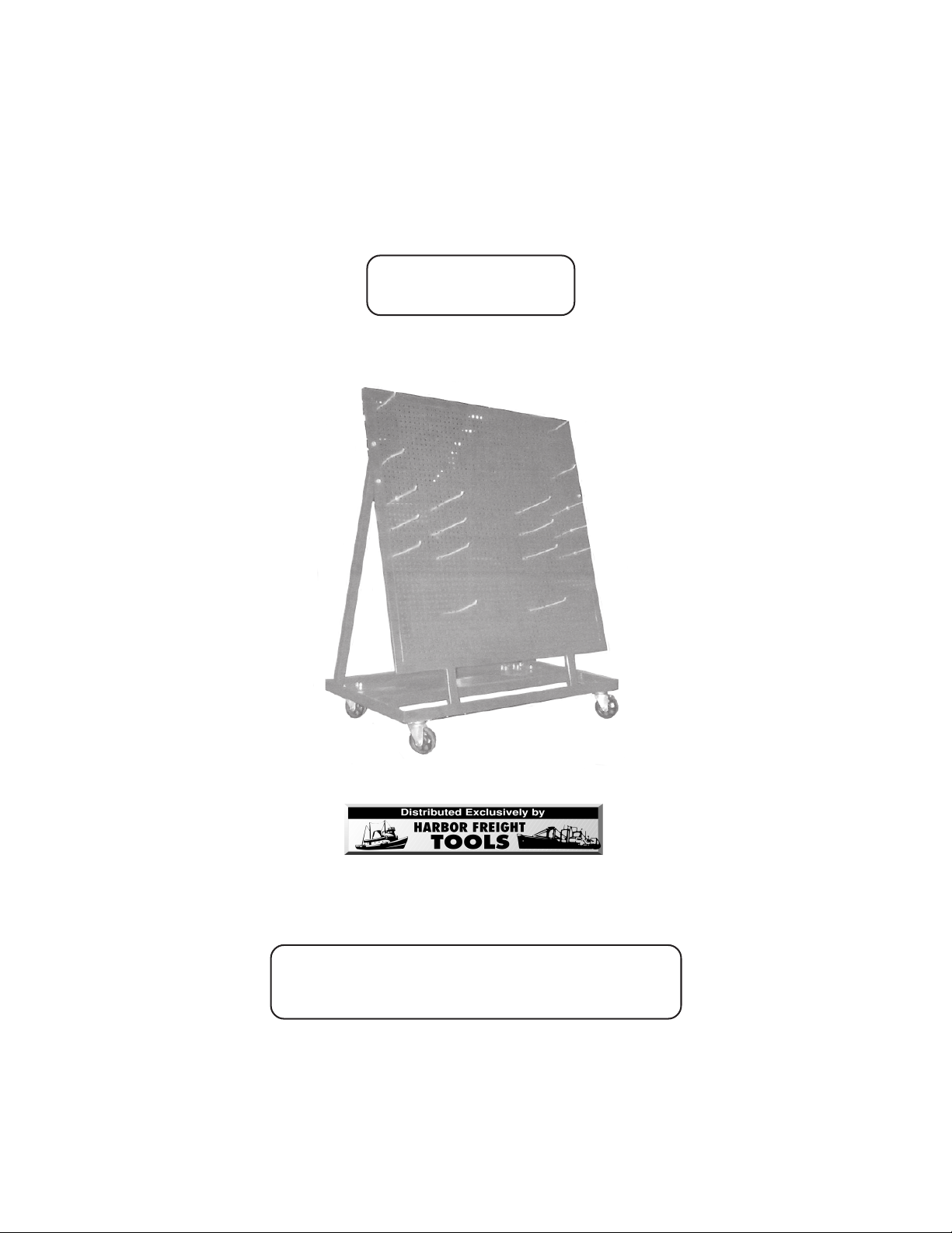
ROLLING TOOL RACK
600 LBS. CAPACITY
Model 94861
ASSEMBLY INSTRUCTIONS
3491 Mission Oaks Blvd., Camarillo, CA 93011
Visit ourWeb site at: http://www.harborfreight.com
Copyright©2006 by Harbor Freight Tools®. All rights reserved. No portion of this
manual or any artwork contained herein may be reproduced in any shape or form
without the express written consent of Harbor Freight Tools.
For technical questions, please call 1-800-444-3353.
®
TO PREVENT SERIOUS INJURY,
READ AND UNDERSTAND ALL WARNINGS
AND INSTRUCTIONS BEFORE USE.
Due to continuing improvements, actual product may differ slighlty from the product described herein.
PRODUCT SPECIFICATIONS
SAVE THIS MANUAL
You will need this manual for the safety warnings and precautions, assembly, operating,
inspection, maintenance and cleaning procedures, parts list and assembly diagram. Keep
your invoice with this manual. Write the invoice number on the inside of the front cover.
Keep this manual and invoice in a safe and dry place for future reference.
GENERAL SAFETY RULES AND PRECAUTIONS
WARNING!
READ AND UNDERSTAND ALL INSTRUCTIONS
Failure to follow all instructions listed below may result in
serious injury.
SAVE THESE INSTRUCTIONS
1. Keep your work area clean and well lit. Cluttered benches, tool racks, and
dark areas invite accidents.
SKU 94861 For technical questions, please call 1-800-444-3353 PAGE 2
2. Stay alert. Watch what you are doing, and use common sense when
operating tools and equipment. Do not use tools and equipment while tired
or under the influence of drugs, alcohol, or medication. A moment of
inattention while operating tools and equipment may result in serious personal
injury.
3. Do not overreach. Keep proper footing and balance at all times. Proper
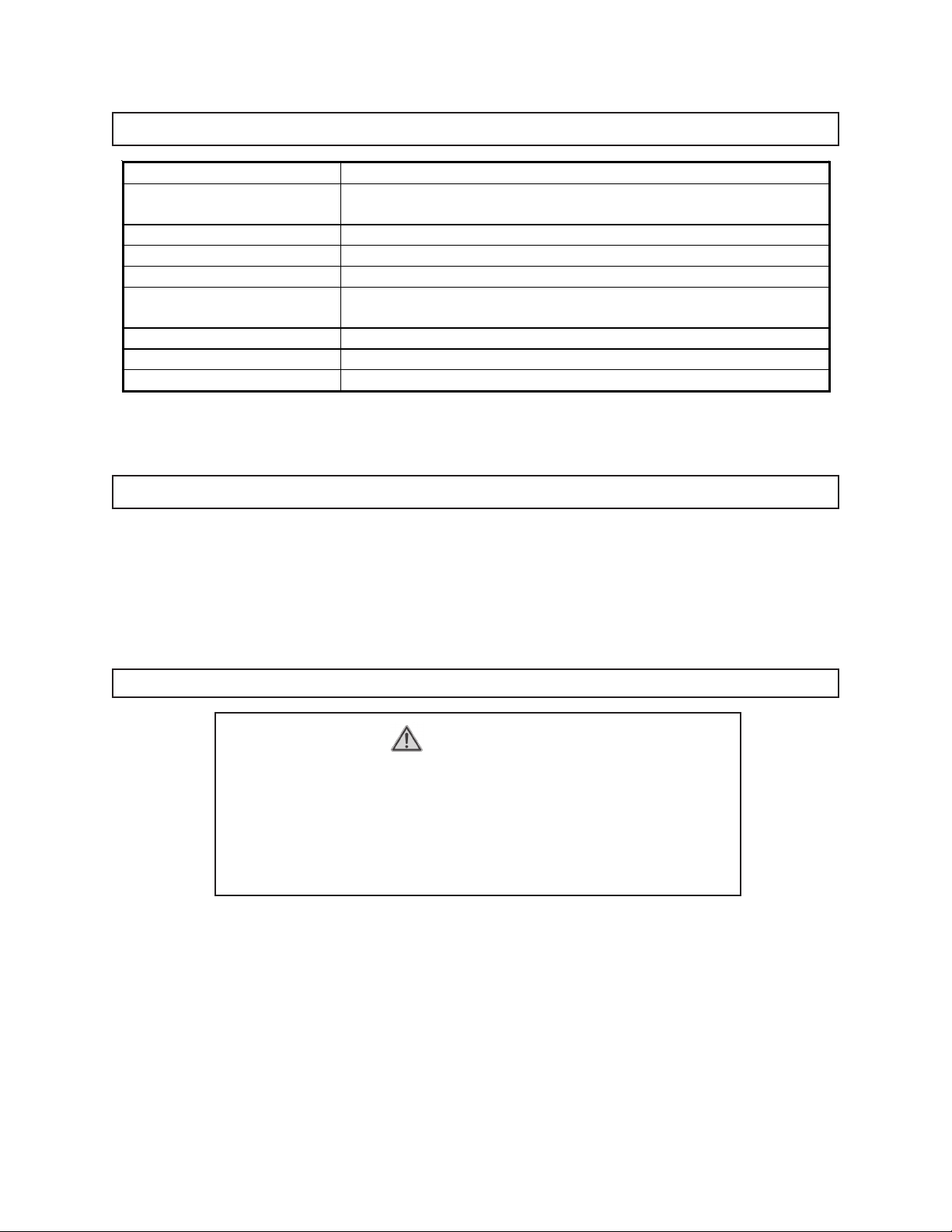
Item Description
Maximum Weight
Capacity 600 Pounds
Peg Board Dimensions 38-1/4” Long x 38-1/4” High x 1/2” Thick
Peg Hole Quantity / Size 48 x 48 (Total: 2,304) / 5/16” Diameters
Base Frame Dimensions 41” Long x 15-1/2” Wide x 1” Deep
Swivel Caster Size / Type 4-1/2’ High x 3-1/2” Diameter
Cast Iron Wheels with Locks (Qty. 2); Without Locks (Qty.2)
Ground Clearance 4-1/2” High
Accessories Hook Pins (Qty. 22) with Threaded Lock Nuts and Washers
Unit Weight 108.35 Pounds

SKU 94861 For technical questions, please call 1-800-444-3353 PAGE 3
footing and balance enables better control of tools and equipment in unexpected
situations.
4. Use safety equipment. Wear eye protection. Wear ANSI approved
safety impact goggles when assembling this product.
5. WARNING! Never exceed the maximum weight carrying capacity
(600 pounds) of the Rolling Tool Rack.
6. Maintain tools and equipment with care. Properly maintained tools and
equipment are less likely to malfunction and are easier to control. Do not use
damaged tools and equipment. Tag damaged tools and equipment “Do not use”
until repaired.
7. Check for misalignment or binding of moving parts, breakage of parts, and
any other condition that may affect the Rolling Tool Rack’s operation. If
damaged, have the tool serviced before using. Many accidents are caused
by poorly maintained tools and equipment.
8. Use only accessories that are recommended by the manufacturer for your
Rolling Tool Rack. Accessories that may be suitable for one product may
become hazardous when used on another product.
12. Do not allow children and other unauthorized people to handle or play with
the Rolling Tool Rack.
13. Never sit or stand on the Rolling Tool Rack. Doing so could possibly cause
the Tool Rack to tip, causing personal injury and/or product damage.
14. Use the right product for the job. Do not attempt to force small products and
equipment to do the work of larger industrial products and equipment. There
are certain applications for which this product was designed. It will do the job
better and more safely at the capacity for which it was intended. Do not modify
this product, and do not use this product for a purpose for which it was not
intended.
9. Follow instructions in the
“Inspection, Maintenance, And Cleaning”
section
of this manual. Use of unauthorized parts or failure to follow maintenance
instructions may create a risk of injury.
10. Maintain labels and nameplates on the RollingTool Rack. These carry
important information. If unreadable or missing, contact Harbor Freight Tools for
a replacement.
11. Industrial applications must follow OSHA guidelines.

SKU 94861 For technical questions, please call 1-800-444-3353 PAGE 4
15. Store idle tools and equipment. When not in use, the Rolling Tool Rack must
be stored in a dry location to inhibit rust. Always lock up the tool and keep out of
reach of children and other unauthorized people.
16. Do not use this product if under the influence of alcohol or drugs. Read
warning labels if taking prescription medicine to determine if your judgement or
reflexes are impaired while taking drugs. If there is any doubt, do not use the
Rolling Tool Rack.
17. Once the Rolling Tool Rack is moved to a desired work location, make sure
to lock the Caster Wheels in position using the Casters’ Locks.
18. WARNING! The warnings and precautions discussed in this manual cannot
cover all possible conditions and situations that may occur. It must be under
stood by the operator that common sense and caution are factors which cannot
be built into this product, but must be supplied by the operator.
SAVE THESE INSTRUCTIONS
UNPACKING
When unpacking, check to make sure all the parts shown on the Parts List on page 8 are
included. If any parts are missing or broken, please call Harbor Freight Tools at the number
shown on the cover of this manual as soon as possible.
ASSEMBLY INSTRUCTIONS
NOTE:
For further references to the parts discussed in this manual,
see the Assembly Diagram and Parts List shown on page 8.
To Attach The Support Booms And Casters To The Base Assembly:
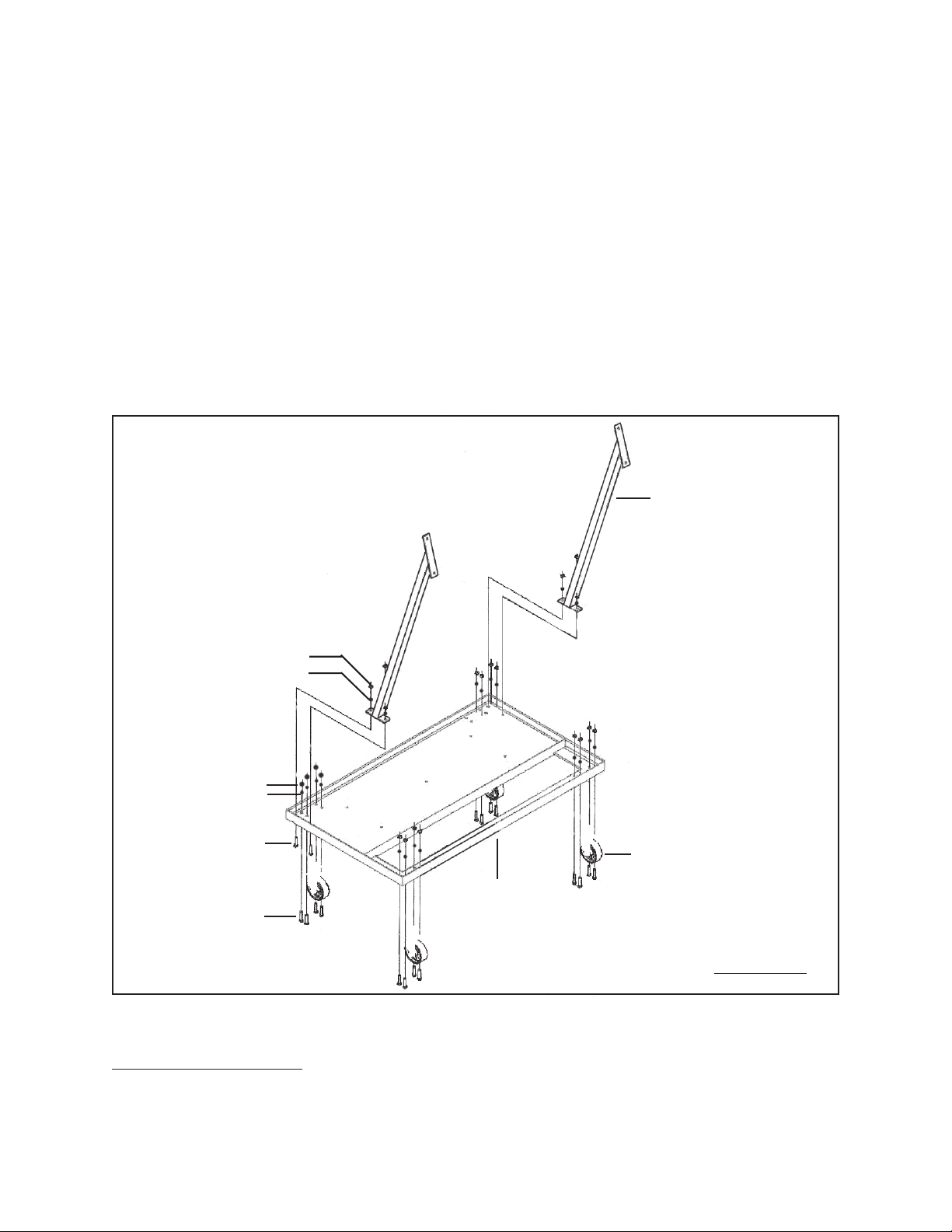
1. Align the
two
mounting holes at the base of each Support Boom (6) with the two
outer
mounting holes in each corner of the Base Assembly (1).
(See Figure A, next page.)
SKU 94861 For technical questions, please call 1-800-444-3353 PAGE 5
2. Insert
two
Hex Bolts (3) upward through the two
outer
mounting hoIes in each
corner of the Base Assembly (1) and through the mounting holes in each of the
two Support Booms (6). Then secure the two Support Booms to the Base
Assembly, using two Spring Washers (5) and two Hex Nuts (4) for each Support
Boom. (See Figure A.)
3. Align the
four
mounting holes in each of the four Casters (2) with the four
mounting holes located in each corner of the Base Assembly (1). (See Figure A.)
4. Insert
four
Hex Bolts (3) upward through the four mounting hoIes in each Caster
(2) and through the four mounting holes in each corner of the Base Assembly
(1). Then secure the four Casters to the Base Assembly, using four Spring
Washers (5) and four Hex Nuts (4) for each Caster. (See Figure A.)
HEX BOLT
(3)
HEX BOLT
(3)
HEX NUT (4)
SPRING WASHER (5)
HEX NUT (4)
SPRING WASHER (5)
FIGURE A
SUPPORT BOOM
(6)
BASE ASSEMBLY
(1)
CASTER
(2)
To Attach The Frame:
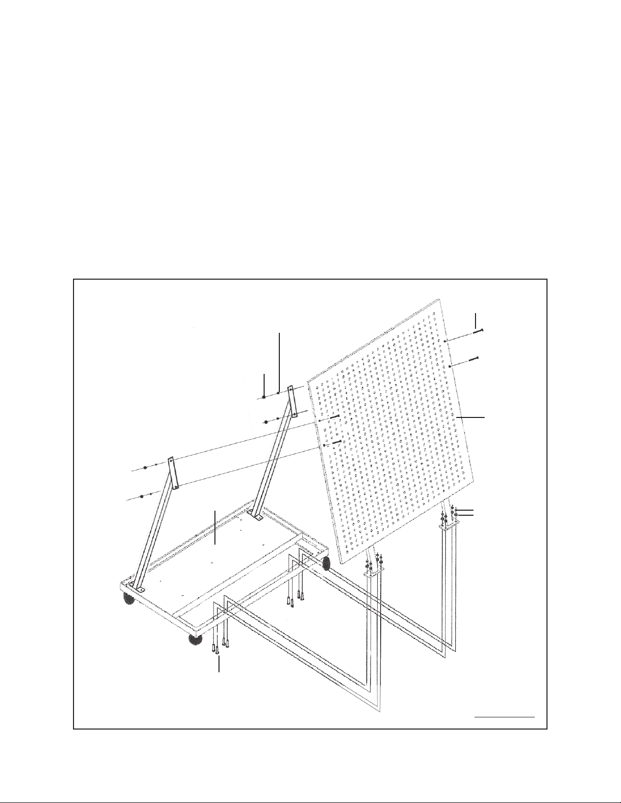
1. Align the four mounting holes located in each leg of the Frame (7) with the four
SKU 94861 For technical questions, please call 1-800-444-3353 PAGE 6
mounting holes located in the front portion of the Base Assembly (1).
(See Figure B.)
2. Insert four Hex Bolts (3) upward through the four mounting holes in the Base
Assembly (1) and through the four mounting holes in the leg of the Frame (7).
Then secure the leg of the Frame to the Base Assembly, using four Spring
Washers (5) and four Hex Nuts (4). Repeat this Step to secure the remaining leg
of the Frame to the Base Assembly. (See Figure B.)
3. Align the two mounting holes in each side of the Frame (7) with the two mounting
holes in each Support Boom (6). Secure the two Support Booms to the Frame,
using two Hex Bolts (8), two Spring Washers (5), and two Hex Nuts (4) for each
Support Boom. (See Figure B.)
HEX
NUT
(4)
SPRING WASHER
(5)
HEX BOLT
(8)
HEX BOLT
(3)
SPRING WASHER
(5)
HEX NUT (4)
FRAME
(7)
BASE ASSEMBLY
(1)
FIGURE B
SKU 94861 For technical questions, please call 1-800-444-3353 PAGE 7
To Install The Hook Pins:
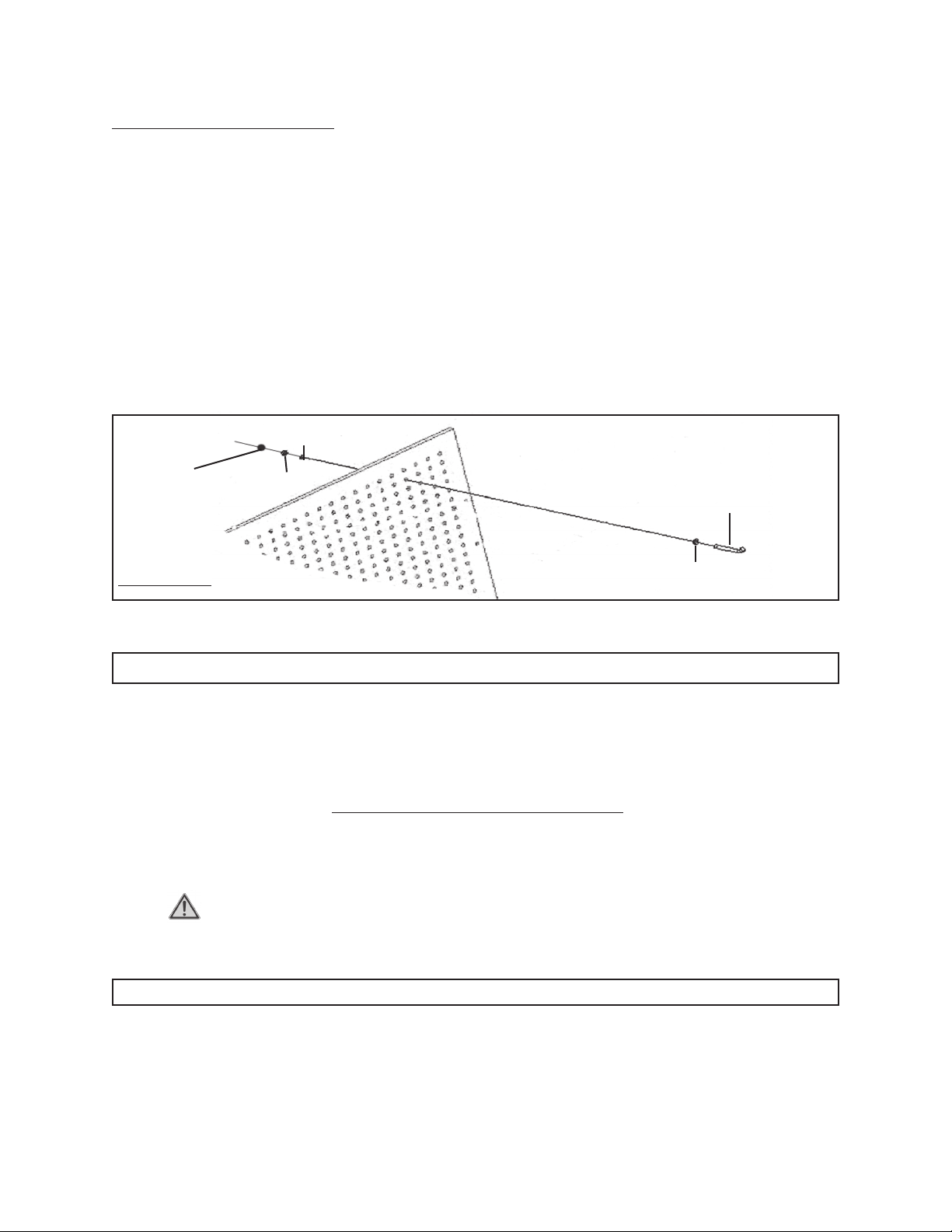
1. Insert one Washer (11) onto the threaded end of a Hook Pin (9, 10).
(See Figure C.)
2. Insert the Hook Pin (9, 10), with its Washer (11) into a Peg Hole in the Frame (7).
(See Figure C.)
3. Secure the Hook Pin (9, 10) to the Frame (7), using one Washer (11), one Spring
Washer (5), and one Hex Nut (4). (See Figure C.)
4. Repeat Steps #1, #2, and #3 above to install the remaining Hook Pins (9, 10).
(See Figure C.)
HOOK PIN
(9, 10)
HEX NUT
(4) SPRING
WASHER
(5)
WASHER
(11)
WASHER
(11)
FIGURE C
INSPECTION, MAINTENANCE, AND CLEANING
1. Before each use: Inspect the general condition of the Rolling Tool Rack. Check
for misalignment or binding of moving parts, cracked or broken parts, loose Bolts
and Nuts, loose Hook Pins, and any other condition that may affect the safe
operation of the Tool Rack. If a problem occurs, have the problem corrected
before further use. Do not use damaged equipment.
2. To clean: Use a clean cloth with a mild detergent. Then dry. Do not use solvents
to avoid damaging the paint finish of the Rolling Tool Rack.
3. CAUTION! All maintenance, service, or repairs not mentioned in this
manual must only be performed by a qualified service technician.
PLEASE READ THE FOLLOWING CAREFULLY
THE MANUFACTURER AND/OR DISTRIBUTOR HAS PROVIDED THE PARTS LIST AND ASSEMBLY DIAGRAM IN THIS MANUAL
AS A REFERENCE TOOL ONLY. NEITHER THE MANUFACTURER OR DISTRIBUTOR MAKES ANY REPRESENTATION OR
WARRANTY OF ANY KIND TO THE BUYER THAT HE OR SHE IS QUALIFIED TO REPLACE ANY PARTS OF THE PRODUCT. IN
FACT, THE MANUFACTURER AND/OR DISTRIBUTOR EXPRESSLY STATES THAT ALL REPAIRS AND PARTS REPLACEMENTS
SHOULD BE UNDERTAKEN BY CERTIFIED AND LICENSED TECHNICIANS, AND NOT BY THE BUYER. THE BUYER ASSUMES
ALL RISKS AND LIABILITY ARISING OUT OF HIS OR HER REPAIRS TO THE ORIGINAL PRODUCT OR REPLACEMENT PARTS
THERETO, OR ARISING OUT OF HIS OR HER INSTALLATION OF REPLACEMENT PARTS THERETO.
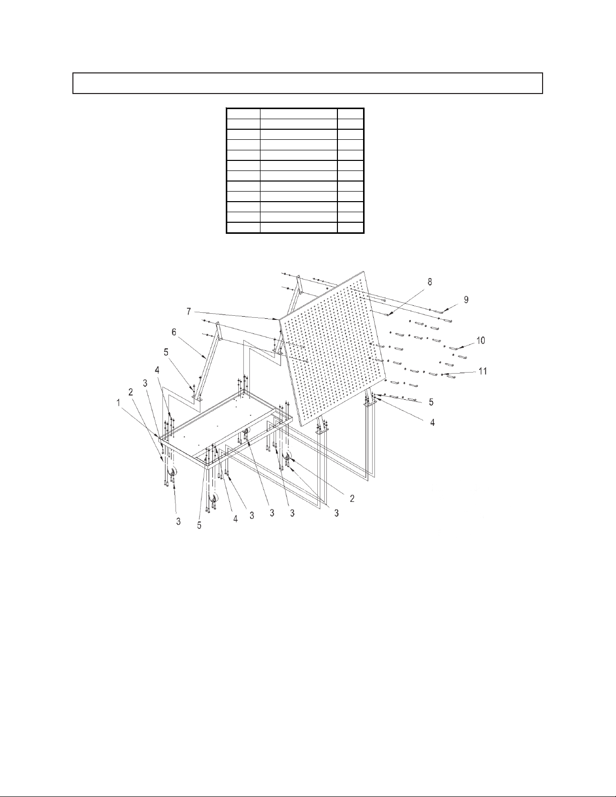
PARTS LIST AND ASSEMBLY DIAGRAM
SKU 94861 For technical questions, please call 1-800-444-3353 PAGE 8
NOTE:
Some parts are listed and shown for illustration purposes only,
and are not available individually as replacement parts.
Part # Description Qty.
1 Base Assembly 1
2 Caster (3.5”) 4
3 Hex Bolt (M8 x 25) 28
4 Hex Nut (M8) 54
5 Spring Washer 54
6 Support Boom 1
7 Frame 1
8 Hex Bolt (M8 x 40) 4
9 Hook Pin 11
10 Hook Pin 11
11 Washer 22
Tabla de contenidos
Otros manuales de Rack y soporte de Harbor Freight Tools

Harbor Freight Tools
Harbor Freight Tools Pittsburgh Motorcycle 64926 Instrucciones de montaje

Harbor Freight Tools
Harbor Freight Tools 95621 Manual de usuario

Harbor Freight Tools
Harbor Freight Tools 91734 Manual de usuario

Harbor Freight Tools
Harbor Freight Tools 91729 Manual de usuario

Harbor Freight Tools
Harbor Freight Tools 69571 Manual de usuario

Harbor Freight Tools
Harbor Freight Tools 92021 Manual de usuario

Harbor Freight Tools
Harbor Freight Tools 90444 Manual de usuario


