Haes Alarm Sense Plus Guía

Installation, Commissioning &
Operating Manual
12 ZONE FULLY FUNCTIONAL REPEATER PANEL
Approved Document UI-ASP-R-01 Issue 3.0
REPEATER PANEL

IMPORTANT NOTE
PLEASE READ THIS MANUAL BEFORE HANDLING THE EQUIPMENT AND
OBSERVE ALL ADVICE GIVEN IN IT
THIS PARTICULARLY APPLIES TO THE PRECAUTIONS NECESSARY TO AVOID
E.S.D
The panel is safe to operate provided it has been installed in compliance with the manufacturer’s instructions
and used in accordance with this manual.
Hazardous voltages are present inside the panel—DO NOT open it unless you are qualied and authorised
to do so. There is no need to open the panel’s enclosure except to carry out commissioning, maintenance
and remedial work. This work must only be carried out by competent service personnel who are fully
conversant with the contents of the panel’s installation manual and have the necessary skills for maintaining
this equipment.
This re alarm system requires periodic checks as specied in BS 5839 Part 1 It is the responsibility of the
system user to ensure it is regularly serviced and maintained in good working order.
Disclaimer
No responsibility can be accepted by the manufacturer or distributors of this re alarm panel for any
misinterpretation of an instruction or guidance note or for the compliance of the system as a whole. The
manufacturer’s policy is one of continuous improvement and we reserve the right to make changes to
product specications at our discretion and without prior notice. E & O E.
IMPORTANT SAFETY NOTES
Haes Systems Ltd, Columbia House, Packet Boat Lane, Cowley Peachey, Uxbridge, UB8 2JP
Model Number
AlarmSense PLUS 12 zone repeater panel ASP-R-12
European Standard EN54-2 : 1997 + A1 : 2006
Control and indicating equipment for re detection and re alarm systems for buildings.
European Standard EN54-4 : 1997 + A1 : 2002 + A2 : 2006
Power supply equipment for re detection and re alarm systems for buildings.
ATTENTION

ASP-R Installation, Commissioning & Operating Manual Approved Document Ref: UI-ASP-R-01 Issue 3.0
1
CONTENTS
Page
ABOUT THIS PANEL 2
PRODUCT OVERVIEW 2
CABINET DETAILS 3
CIRCUIT BOARDS 4
MAIN PCB TERMINALS 5
COMMS PCB TERMINALS 5
TECHNICAL SPECIFICATION 6
POWER SUPPLY MODULE 7
INSTALLATION 8
SAFETY 8
ESD PRECAUTIONS 9
GENERAL 9
MOUNTING THE CABINET 9
MAINS CONNECTIONS 10
CONNECTING THE BATTERIES 11
CABLING 12
SETUP & PROGRAMMING 14
INSTALL COMMS PCB 14
SET NUMBER OF REPEATER PANELS 16
REPEATER PANEL ADDRESSING 16
PROGRAMMING REPEATER PANELS 17
OPERATING 18
PANEL CONTROLS & INDICATIONS 18
DISABLE MODE 20
TEST MODE 21

ASP-R Installation, Commissioning & Operating Manual Approved Document Ref: UI-ASP-R-01 Issue 3.0
2
ABOUT THIS PANEL
PRODUCT OVERVIEW
The AlarmSense PLUS repeater panels have the same, easy to use, controls and indications as the main
control panel but mounted in a smaller cabinet.
The repeaters are fully functional with ‘Silence’, ‘Resound’ and ‘Reset’ controls, as well as Disable and
Test Mode functions. AlarmSense PLUS panels can support up to 8 repeater panels.
Repeater panels are designed to be wired in a fault tolerant (fail safe) loop conguration, from comms A
to B and back to the main panel again. This enables repeater panels to still work if there is a break in the
cables.
If replacing an older system where the existing cabling cannot be congured in a loop as above, it is
possible to re-programme the panel back to legacy RS485 circuit comms monitoring. This then allows any
topology of comms cabling to be utilised.
The main circuit board has 2, switch –ve, inputs which can be used to sound or pulse the alarms. These
inputs can also be re-programmed for use as PSU fault inputs.
The internal comms PCB has 6, switch –ve, programmable outputs.
Different key types are used for the door lock and the ‘activate controls’ key-switch. It is also possible
to enable the controls via a 4 digit code entry if preferred. An eight button keypad is used to control the
system and allow access to the function options (unless disabled).
The control panel comprises of a sheet steel enclosure suitable for wall mounting with a hinged, lockable
front access door. It can be semi recessed, using a suitable recessing bezel. Cable entry is via 20mm
‘knockouts’ located at the top and rear of the cabinet.
The repeaters are supplied with a 1.5 amp internal power supply module. This module complies with the
requirements of EN54-4 : 1988 and provides temperature compensated battery management charging.
Quiesecent and alarm current details for standby battery calculations
Standby Current Alarm Current
ASP-R-12 repeater panel 63mA 85mA

ASP-R Installation, Commissioning & Operating Manual Approved Document Ref: UI-ASP-R-01 Issue 3.0
3
ABOUT THIS PANEL
CABINET
57mm 80mm
260mm
308mm
250mm
300mm

ASP-R Installation, Commissioning & Operating Manual Approved Document Ref: UI-ASP-R-01 Issue 3.0
4
ABOUT THIS PANEL
CIRCUIT BOARDS
AlarmSense PLUS repeater panels comprise of three circuit boards
PSU
@ + +
- - + -
+ -
+ - + - + - + - + -
28V 0V
C NC NO C NC NO
FIRE FAULT FR FLT CC PUL
-OP -OP -IP -IP
SNDR1 SNDR2 ZONE1 ZONE2 ZONE3 ZONE4
BATTERY
COMS A COMS B 28
V+
SW -ve OUTPUTS
+ - + -
1 2 3 4 5 6
1 2 3 4
ON
ADDRESS
1 2 3 4 ENTER
RESOUND SILENCE RESET
TPCA01-R - Master PCB
TPCA05 - Comms PCB (with V3.0 software)
TPCA03 - LED Display & Controls PCB
• Piggy backs on Main PCB
• 6 programmable switch -ve outputs
ASP-R Installation, Commissioning & Operating Manual Approved Document Ref: UI-ASP-R-01 Issue 3.0
5
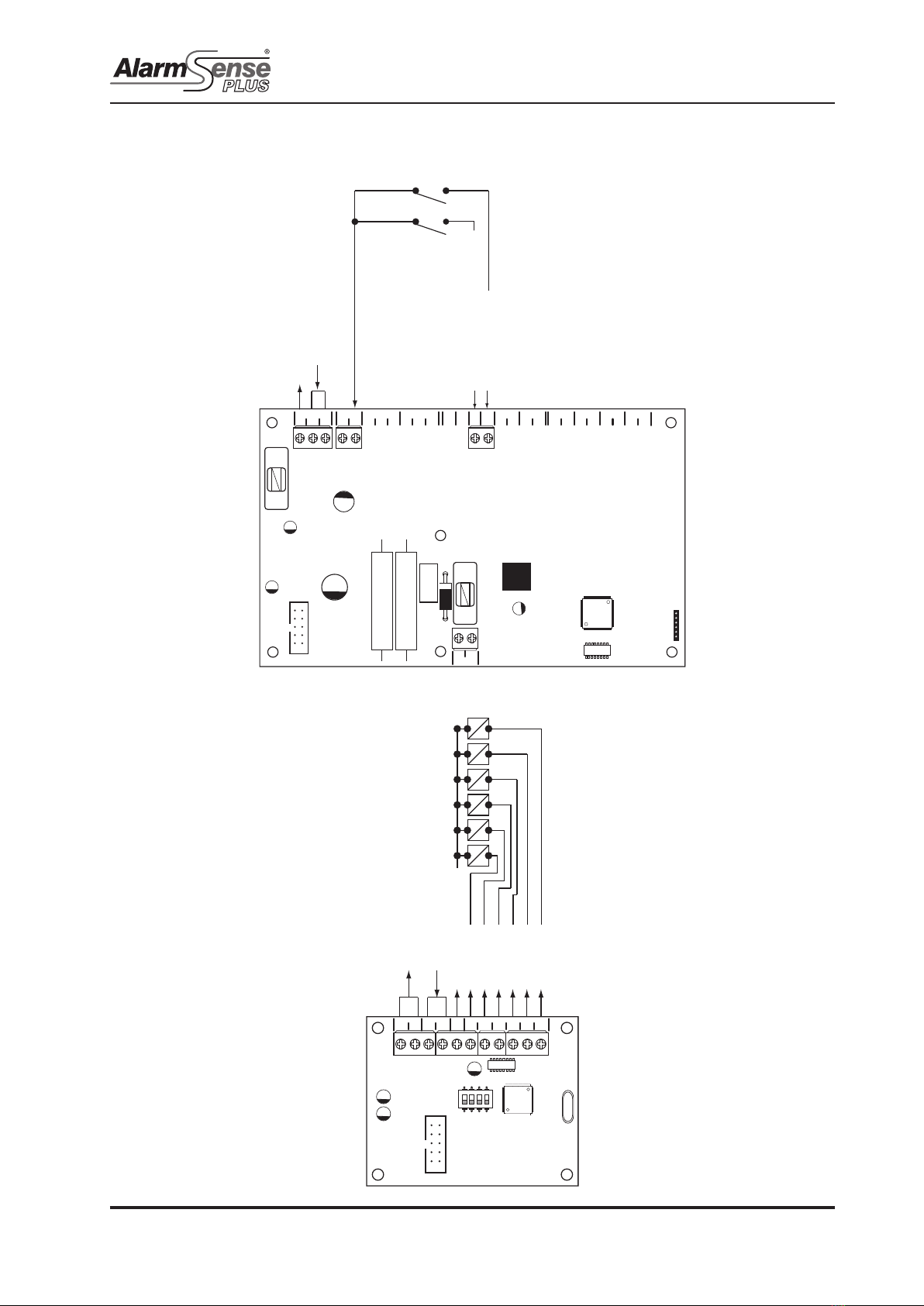
ABOUT THIS PANEL
MAIN PCB TERMINALS
COMMS PCB TERMINALS
PSU
@ + +
- - + -
+ -
+ - + - + - + - + -
28V 0V
C NC NO C NC NO
FIRE FAULT FR FLT CC PUL
-OP -OP -IP -IP
SNDR1 SNDR2 ZONE1 ZONE2 ZONE3 ZONE4
BATTERY
28v input for power supply
Temperature compensation voltage control link
Alert (pulses sounders)
Precint/class change (activates sounders)
Switched -ve inputs
Switched -ve outputs
Max load 40mA
To 0 volts
COMS A COMS B 28
V+
SW -ve OUTPUTS
+ - + -
1 2 3 4 5 6
1 2 3 4
ON
ADDRESS
Comms output to next panel
Comms input from previous panel
28v output fused @ 500mA
Switch -ve O/P
Switch -ve O/P
Switch -ve O/P
Switch -ve O/P
Switch -ve O/P
Switch -ve O/P
Relay Coil

ASP-R Installation, Commissioning & Operating Manual Approved Document Ref: UI-ASP-R-01 Issue 3.0
6
ABOUT THIS PANEL
General Specication
Enclosure Steel IP30. Epoxy powder coated Interpon Radon, silver grey
Cabling The use of re resistant screened cable, is recommended, FireBurn,
FP200 or equivalent. Minimum size 1mm2. Max cable length 1Km
Non re resistant cable can be used, BELDEN 9271 or BELDEN 9860.
Maximum cable length 1.2Km
Temperature range -5 deg C to +40 deg C max RH 95%
TECHNICAL SPECIFICATION
Electrical Specication Inputs & Outputs - TPCA01-R Main PCB
Terminal capacity 0.5mm2 to 2.5mm2solid or stranded wire.
PSU @ output Power supply voltage control line. For temperature compensation control.
PSU Input + - 28vdc supply input. Diode protected for
reversal and independent short circuit.
Max current 3 amps.
Max input current 3 amps. Input voltage
22vdc to 32vdc.
Inputs; CC, PUL Switched -ve inputs, connect to 0v to
trigger. Max input voltage = 28vdc. Non
latching, max resistance 100R.
Protected via 10K Ohm impedance, 3v6
zener diode.
Electrical Specication Inputs & Outputs - TPCA05 comms PCB
Comms A - B RS485 Repeater Comms, fused @ 20mA
28v Supply output Fused @ 500mA
Programmable outputs 1 - 6 Switched -ve outputs Overload voltage protected to 52vdc
Current limited 680R
Max load = 40mA

ASP-R Installation, Commissioning & Operating Manual Approved Document Ref: UI-ASP-R-01 Issue 3.0
7
ABOUT THIS PANEL
POWER SUPPLY MODULE
Power Supply Specication
Mains supply 230vac +10% / -15% 50Hz max current
1A
Mains supply fuse 2 Amp (T2A 250V) Not accessible for servicing. Internal to
switch mode power unit
Internal power supply rating 1.5 Amps total including battery charging Maximum load shared between outputs
= 900mA
Maximum continuous load for battery
standby (ImaxA)
ImaxA = 575mA ImaxB not specied
Minimum current drawn by repeater
panel
I min = 63mA
Maximum ripple 250 millivolts Supply and charger fault monitored
Min/max battery size and type 2 x 3.2Ahr 12volt VRLA
Use Yuasa NP range batteries
Other equivalent batteries may be
used but have not been tested for the
purposes of EN54 approval.
Battery charging voltage 27.3 vdc nominal at 20 deg C Temperature compensated
Battery charging output current 1.5A PSU 630mA
Current limited 10 Ohms
Battery high impedance fault (Batt Hi Z) Resistance > 1 Ohm 1 hour reporting time
Max current drawn from batteries 1.5 Amps with main power source
disconnected. Battery fuse 3A LBC
20mm.
V+
V-
E
N
L
24v +ve output
O/P Voltage adjust
(default setting 27v4 at 20oC)
24v -ve output
Earth
Neutral
Live
Mains input
Temperature compensation input
from @ terminal on main PCB

ASP-R Installation, Commissioning & Operating Manual Approved Document Ref: UI-ASP-R-01 Issue 3.0
8
INSTALLATION
SAFETY
Suppliers of articles for use at work are required under section 6 of the Health and Safety at Work Act 1974
to ensure as reasonably as is practical that the article will be safe and without risk to health when properly
used. An article is not regarded as properly used if it is used “without regard to any relevant information or
advice” relating to its use made available by the supplier.
It is assumed that the system, of which this control panel is a part, has been designed by a competent re
alarm system designer in accordance with BS 5839 Part 1 and with regard to BS EN 54 parts 2 and 4 in
the case of control equipment and power supplies. Design drawings should be provided to clearly show
the position of any eld devices and ancillary equipment.
This product should be installed, commissioned and maintained by, or under the supervision of, competent
persons according to good engineering practice and,
(i) BS 7671 (IEE wiring regulations for electrical installations)
(ii) Codes of Practice
(iii) Statutory requirements
(iv) Any instructions specically advised by the manufacturer
According to the provisions of the Act you are therefore requested to take such steps as are necessary to
ensure that any appropriate information about this product is made available by you to anyone concerned
with its use.
This equipment is designed to be operated from 230V AC 50/60 Hz mains supplies and is of Class I
construction. As such it must be connected to a protective earthing conductor in the xed wiring of the
installation. Failure to ensure that all conductive accessible parts of this equipment are adequately bonded
to the protective earth will render the equipment unsafe.
This equipment must only be installed and maintained by a suitably skilled and technically
competent person.
THIS IS A PIECE OF CLASS 1 EQUIPMENT AND MUST BE EARTHED
These panels are designed to comply with the requirements of EN 54 part 2.
Installation of the panel should only be carried out by qualied personnel. The electronic components
within the panel can be damaged by static charge. Suitable precautions must be taken when handling
circuit boards. Never insert or remove boards or components, or connect cables, with the mains power
on or batteries connected.
Equipment Guarantee
This equipment is not guaranteed unless the complete system is installed and commissioned in accordance with the laid
down national standards by an approved and competent person or organisation.
This product has been manufactured in conformance with the requirements of all applicable EU Council
Directives
Otros manuales para Alarm Sense Plus
1
Tabla de contenidos
Otros manuales de Reloj de repetición de Haes


