Grin Cycle Analyst V3.1 Manual de usuario

Cycle Analyst V3.1
Official User Manual
Grin Technologies Ltd
Vancouver, BC, Canada
ph: ( 04) 5 9-0902
email: [email protected]
web: http://www.ebikes.ca
Copyright © 2019

Cycle Analyst V3.1 User Manual
Rev 1.0
Table of Contents
1 Introduction...................................................................................3
2 High Level Operation....................................................................3
3 Installation....................................................................................4
3.1 Handlebar Wiring.....................................................................................4
3.2 Shunt / Controller Wiring.........................................................................6
4 Display Screens.............................................................................7
4.1 ain Display..............................................................................................7
4.2 Diagnostics Screen, Display #12...............................................................8
4.3 Wh/km, Display #4....................................................................................9
5 esetting the Trip Counter............................................................9
6 Setup Menu..................................................................................10
6.1 Accessing and Navigating the Setup enu ...........................................10
6.2 Setting the Speedometer..........................................................................11
6.3 Setting Up the Battery.............................................................................14
6.4 Throttle Input Settings............................................................................17
6.5 Output Throttle Settings.........................................................................19
6.6 Setup Speed Limits..................................................................................19
6.7 Setup Power Limits.................................................................................20
6.8 Setting Up PAS or Torque Sensors........................................................21
6.9 PAS Configuration..................................................................................22
6.10 Temperature Sensor..............................................................................24
6.11 Setup Auxiliary Control Inputs............................................................25
6.12 Setup Ebrakes and Regen. ...................................................................27
6.13 Set Current Sense Shunt Resistance....................................................28
6.14 Using Presets..........................................................................................30
6.15 Display Customization..........................................................................31
7 Data Logging...............................................................................31
8 Software Setup Utility .................................................................33
9 Common Mistakes.......................................................................34
10 Enjoy your ide and emember to eset..................................35
11 Specifications.............................................................................36
2
Cycle Analyst V3.1 User Manual
Rev 1.0
1Introduction
Thank you for the purchase of a V3 Cycle Analyst device, Grin's latest model of
open standard display and control device for ebikes and other electric vehicles.
This document should help you get reasonably familiar ith the basic setup and
operation of a CA3 as part of your vehicle system.
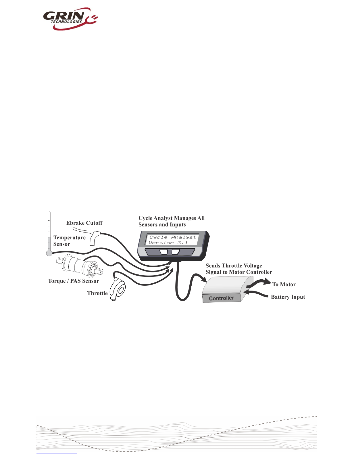
2High Level Operation
The V3 Cycle Analyst is not like a typical ebike display interface that
communicates ith one particular model of motor controller. Instead the CA3 is
designed as a more universal display and control unit. To achieve this
universality, it reads existing signals already present in most EV drives to sense
the po er and speed of the vehicle, and then it regulates the motor po er
through a common throttle signal.
This is an important concept to understand; the CA3 does not "communicate"
ith your ebike in the same manner as proprietary display units. Rather it taps
into analog signals already present inside a motor controller and interprets them.
It then sends hat it thinks is the most appropriate throttle voltage to your
controller for generating a target amount of po er from the motor.
As far as your motor controller kno s, the V3 Cycle Analyst is just a throttle
device. The CA3 can't change any internal controller settings, or make the
controller do anything more than hat you could do via deft manipulation of a
normal throttle.
3
Cycle Analyst V3.1 User Manual
Rev 1.0
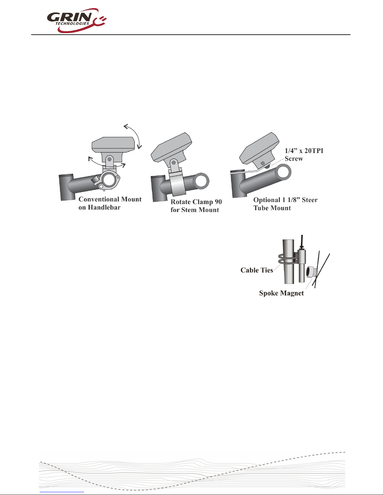
3Installation
The Cycle Analyst includes a handlebar bracket that allo s it to clamp on any
tube from 21mm (7/8”) to 40mm (1.5”) in diameter. You can mount it directly on
the handlebar, or you can s ivel the base 90 degrees and clamp it to the stem
for a more central display that doesn’t consume bar real estate. There is also an
optional steer tube mounting bracket and a ¼” threaded insert on the bottom of
the enclosure for improvised attachments.
If you have a CA3-DPS device hich uses an
external spoke magnet and separate speedometer
sensor, then you ill need to scre the spoke
magnet to your heel and zip-tie the sensor pickup
to your fork so that the magnet passes ithin about
5mm from the middle of the pickup sensor. To avoid
glitches in the speed reading, the sensor body
should be perpendicular to the direction of magnet
motion.
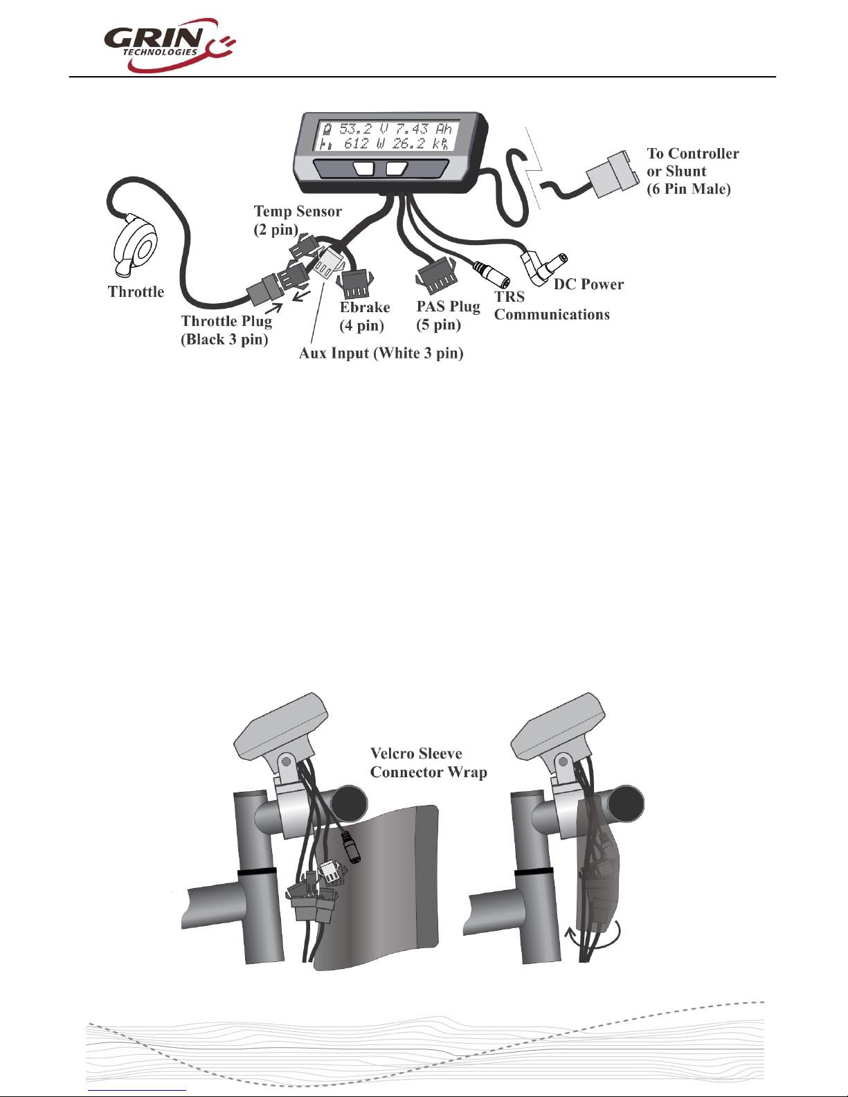
3.1 Handlebar Wiring
It is important that you ire up your throttle to plug into the Cycle Analyst rather
than directly to your motor controller. The CA3 has a short cable bundle for all
accessories and the throttle input is the black 3-pin connector. Your throttle
should be attached to this plug.
You can also connect ebrake cutoffs, auxiliary inputs, a temperature sensor, and
Pedal Assist (PAS) or torque sensors if you have them to the appropriate
connectors on CA3, but the throttle is the most essential for basic operation.
4
Cycle Analyst V3.1 User Manual
Rev 1.0
There are t o additional short cables coming out of the Cycle Analyst. One is an
1/8” TRS communications jack that can be used for data logging or connecting to
a computer for firm are updates and setting changes. The other is a DC Po er
cable that has full battery voltage for po ering front ebike lights, DC-DC
converters, and other peripherals that can run directly off pack voltage.
This DC po er tap is fused internally and is limited to 1 amp. It is shipped ith a
rubber protective cap and you should leave this cap in place if you are not using
the connector, as there is full battery voltage present on the exposed connector
pin.
We include a stretchy fabric Velcro sleeve that lets you cover up the connector
assembly for a clean finished look on the front of your bike once everything has
been plugged in. This sleeve also provides a convenient place for bundling up
any excess cable length.
5
Cycle Analyst V3.1 User Manual
Rev 1.0
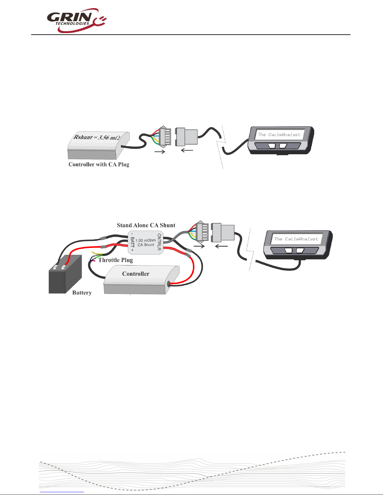
3.2 Shunt / Controller Wiring
For systems that have a CA3 compatible motor controller, the electrical hookup is
simply a matter of connecting the 6-pin CA plug to the mating plug on the
controller. This JST-SM connector standard has pins for the battery voltage,
throttle signal, speedometer signal, and current sense resistor leads.
If your controller doesn't have a compatible CA plug on it, then you ill need to
use the Stand Alone Shunt ired inline ith the + and – battery leads in order for
the CA to see the battery current and voltage.
The Stand Alone CA3 Shunt has a short unterminated cable ith 3 signal ires
in it. The green signal ire is the throttle output of the Cycle Analyst, and that
should be ired to the throttle input plug of your motor controller. Without this
connection, the CA3 can monitor and display speed and battery consumption but
has no ay to regulate and control the motor po er.
The CA3 turns on henever there is voltage on the CA plug. With direct plug
connections, if the controller has an on/off s itch this ould also turn the CA on
and off. If the controller does not have an on/off s itch or the Stand Alone CA
shunt is used, then the the battery itself should have an on/off s itch for turning
the CA on and off.
Please refer to section 6.13 about setting the Cycle Analyst Rshunt value,
especially if you are connecting the CA3 directly to a motor controller.
6

Cycle Analyst V3.1 User Manual
Rev 1.0
4Display Screens
When the device is po ered up you can scroll through numerous display screens
by pressing the left and right buttons to sho you things of interest:
Table 1: Summary of CA3.1 Display Screens
Display #1, Main Screen Summary of battery level, speed, power, voltage, distance etc.
Display #2, Electrical nly View of just t e battery voltage, current, power, and amp- ours
Display #3, Human Power S ows pedal cadence and uman power if torque sensor installed
Display #4, Wh/km Battery watt- ours and energy consumed per km or mile
Display #5, Human Stats Average uman power, pedal cadence, and total uman energy output
Display #6, % Regen S ows regenerative amp- ours and % by w ic it as extended your range
Display #7, Peak Stats S ows peak current, peak regen current, and battery voltage sag
Display #8, Speed Stats Maximum and average trip speed and total trip time
Display #9, Temp Stats S ows current, average, and maximum temperatures if sensor is attac ed
Display #10, dometer S ows bot current trip distance and lifetime odometer
Display #11, Batt Info C arge cycle count, total kW energy used, and Battery internal resistance
Display #12, Diagnostics Live readout of t rottle input/output voltages and active limiting flags
Most of the essential information you ould ant hile riding is on Display #1.
4.1 Main Display
The battery State Of Charge (SOC) icon on the top left is a graphical indication of
the charge level in your battery pack, inferred from a combination of the cell
chemistry, pack voltage, and amp-hour consumption. This gauge ill only be
accurate if the battery type and series cell count has been set up correctly.
Next to that is the actual pack voltage. We recommend paying attention to your
battery voltage and becoming familiar ith the value that it sho s on a full
7

Cycle Analyst V3.1 User Manual
Rev 1.0
charge, during use, and hen the battery goes flat. This is often your first clue to
anomalous behavior and provides very useful troubleshooting information.
The top right is a customizable display field. By default, this toggles bet een
sho ing your accumulated amp-hours and distance since the last trip reset, but it
can be configured to sho other things like motor temperature, instantaneous
h/km, pedal cadence and so forth. You ill eventually find the consumed amp-
hours to be among the most useful and important pieces of information on the
CA display, but only if you remember to do a trip reset each time there is a fresh
charge on the battery pack.
The bottom left of the display has a throttle position that moves up and do n ith
the user's throttle signal going into the Cycle Analyst. This is replaced by an
animated brake lever if the ebrake cutoffs are engaged. Just beside this slider is
an animated Pedal Assist bar graph, hich is only active if you have a PAS
sensor and visually indicates ho fast or hard you are pedaling.
The bottom left numeric display by default sho s the electrical po er currently
flo ing through the system, and ill go negative during regenerative braking. It
is possible to change this to display amps instead of atts if you prefer.
Finally, on the bottom right is a readout of your current vehicle speed, in either
kph or mph as chosen in the setup menu.
The left and right buttons ill scroll through other display screens that sho
specific information that may be of interest. These screens are explained in detail
on the CA3 eb page and any of them can be hidden from vie if desired. The
diagnostics screen and att-hour screen are of particular interest though.
4.2 Diagnostics Screen, Display 12
If you press the left button once from the main display, you ill have the
diagnostics display. This can be invaluable during any kind of system
troubleshooting. The top line sho s the actual throttle voltage signal going into
the CA3, as ell as the throttle voltage going out to your motor controller. If the
rate of change of the throttle is being clamped, then the associated rate limit ill
sho up (F = fast, U = up, P = PAS, D = do n, see section 6.5).
8
Cycle Analyst V3.1 User Manual
Rev 1.0
The bottom left sho s if any of the limit settings are actively regulating the
throttle output voltage. Letters awvst refer to the Amps, Watts, lo Voltage,
Speed, and Temperature rollbacks, and they become capitalized hen active.
This display lets you easily identify if your input throttle is orking correctly, if the
CA itself is sending an output throttle to the motor controller, and if that output
throttle is being clamped by any of the programmed limit settings.
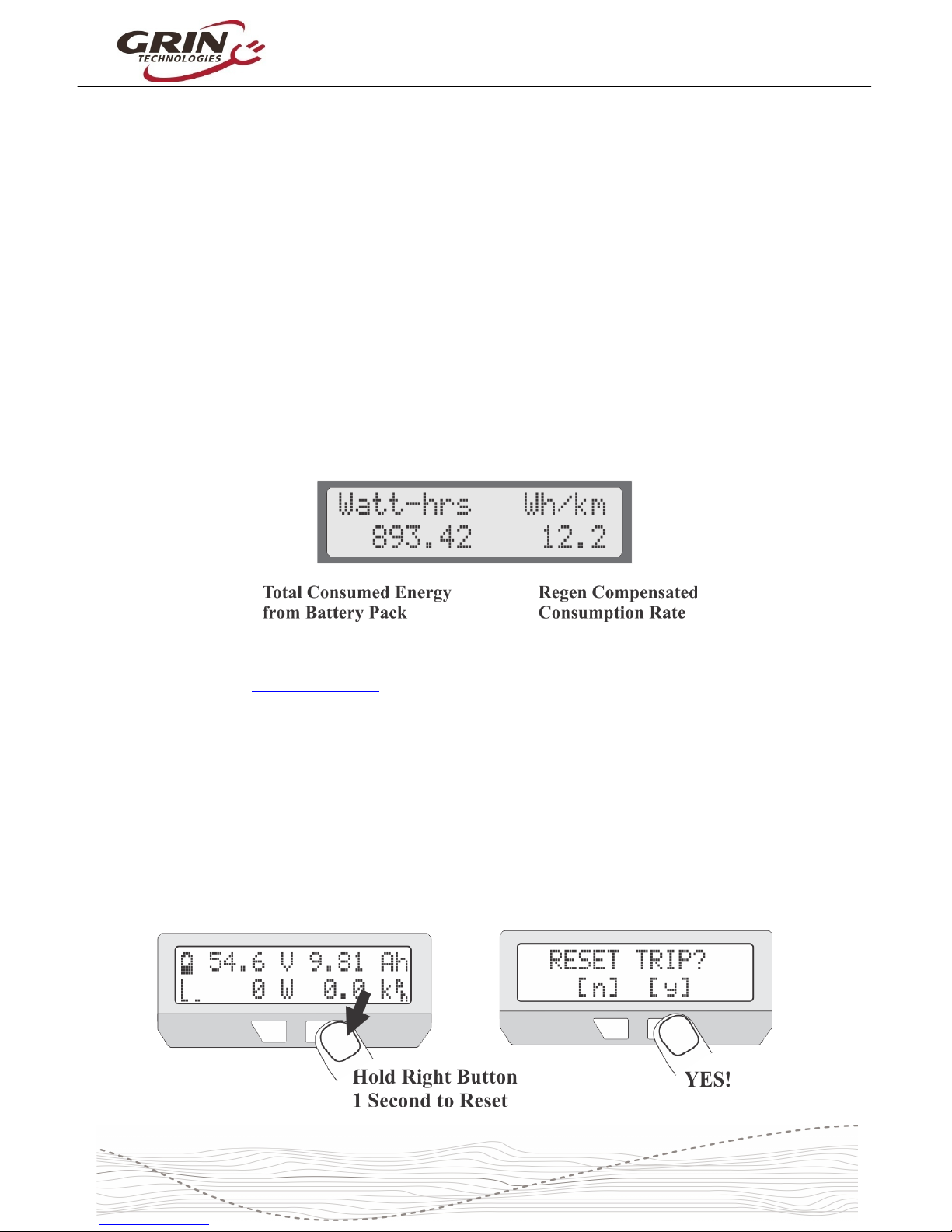
4.3 Wh/km, Display 4
The 4th display screen sho s the total energy in att-hours taken from the
battery, as ell as the average att-hours used per distance traveled, either
h/km or h/mi. This is one of the most useful statistics to check as it is the
equivalent of fuel mileage for your electric vehicle. You can see ho different
riding styles and terrains affect your energy usage, and you can compute ho
large of a battery ill be required to travel a given distance.
The other 9 displays are largely self explanatory and are more thoroughly
covered on the CA3 info page.
5Resetting the Trip Counter
If there is only one thing to remember about using the Cycle Analyst, it is that you
ill ant to make a habit of resetting the Cycle Analyst every time you have a
fresh charge in the battery. Do this by pressing and holding the right button until
the message "RESET TRIP?" sho s on the screen. This allo s you to see your
consumed battery amp-hours on each trip and ensures that the battery cycle
statistics are accurate.
9
Cycle Analyst V3.1 User Manual
Rev 1.0
If you forget to reset, the trip amp-hour, att-hour, and distance accumulators ill
eventually peg at their maximum values and you'll stop accumulating ne
statistics. You also on't get the benefit of seeing an accurate battery charge
cycle count, seeing trip to trip variation in your h/km consumption stats, and
learning exactly ho many amp-hours the battery is able to deliver.
If you press the reset button on certain other display screens, it ill reset just the
statistics associated ith that screen, like a reset of just the peak statistics or just
the temperature data.
6Setup Menu
If you received your CA3 as part of a complete ebike kit package then it should
be pre-configured ith reasonable values for that setup and be ready to ride.
There should be little need to change anything. If it as received as an
independent device and not as part of a kit package, then there is a good chance
that you ill need to change a number of settings in the CA3’s setup menu for it
to function ith accurate readings. Most essential ould be the heel size,
battery details, and Rshunt value.
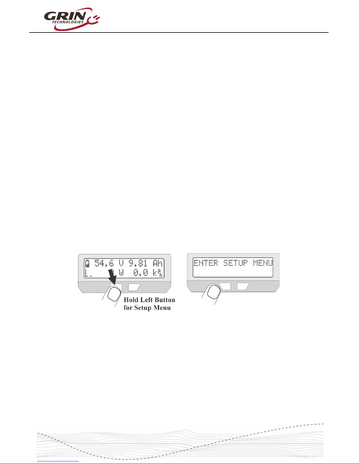
6.1 Accessing and Navigating the Setup Menu
The Setup Menu is accessed by pressing and holding the left button.
Once you are in the setup menu, the left and right buttons allo you to scroll
through the options or toggle digits up and do n. Pressing and holding the
buttons has a special effect.
Hold the RIGHT button to enter a menu or save a setting (like pressing
enter on a keyboard).
Hold the LEFT button to exit something (like pressing escape on a
keyboard).
The setup page is organized ith all the related settings grouped into sub-
menus. Each of these high level menus is summarized in the table belo .
10
Tabla de contenidos
Manuales populares de Accesorios para bicicletas de otras marcas

Sigma
Sigma BC 16.16 Manual de usuario

Playcore
Playcore Dero Setbacks Manual de usuario

VDO Cyclecomputing
VDO Cyclecomputing x3dw Manual de usuario

Cateye
Cateye RAPID X2 Manual de usuario

buratti meccanica
buratti meccanica Clorofilla Trail Manual de usuario

Shimano
Shimano SG-8R20 Instrucciones de funcionamiento


