GrassFlap 42B Manual de usuario

GrassFlap.com Phone: (502) 594-3546 Rev 10.2021
Parts List
10-99-33
Hinge Plate Exmark
10-99-11
Flap Spring
10-99-31
Low Prole
Spring Mount
10-99-22
Clevis Pin
10-99-34
Exmark Flap
Mount
10-99-28
Bushing Cable Pin
Flap End
10-99-32
Bushing
Spring Bolt
GrassFlap 42B Installation Guide
10-99-52
Bushing Kit for Flap Hex
10-99-51
Bushing Kit for Pedal Hex
10-99-07
Cable 70 Inch 10-99-35
SE Pedal Assembly
10-99-21
Clevis Kit
10-99-07
Cable 70 Inch
10-99-51
Bushing Kit for
Pedal Hex
10-99-13
RE Pedal Assembly 10-99-41
SEL Pedal Assembly
10-99-08
Cable 50 Inch
10-99-21
Clevis Kit
Cable
Tie

Grass
Flap
grassflap.com
Instruction videos available online at
http://www.youtube.com/user/GrassFlap
and at GrassFlap.com
PLEASE READ!
If you are having ANY ISSUES
with assembly or operation.
Please contact us at:
(502) 594-3546
or
david@grassap.com
STEP 1

STEP 2
(2x)
AB
A) Remove factory discharge chute, save bolts for later use.
B) Remove belt cover.
GrassFlap 42B Assembly Instructions
GrassFlap.com Phone: (502)594-3546 3
STEP 3
Exmark No-Drill Mount
10-99-35
2x
Install no drill mount.
Position as shown. Use bolts from step 1 or
(2) 3/8” x 1” bolts provided.
Use hammer to tap mount in place if tight (no drill
mount will be snug on walk-behind mower.)
Tools List
Wrench - 7/16”, 1/2” & 9/16”
Socket
1/2” & 9/16”
Drill Bit - 11/32” & 1/2”
Pliers
Center Punch
Zip Ties
Hammer
Drill

STEP 4
STEP 5
A (2x)
B
Mount ap assembly to no-drill.
A) Use (2) 3/8” x 1“ bolts provided.
B) Make sure the ap is ush with opening
and tighten bolts.
STEP 6
Connect ap spring.
Use a small box end wrench to hook spring over
bushing spring bolt on hinge assembly.
GrassFlap 42B Assembly Instructions
GrassFlap.com Phone: (502)594-3546 4
A
B
Bolt On Spring Mount
A) Place spring mount on ap so large hole on spring
mount ts over nut on pivot bolt (do not loosen pivot
bolt nut).
B) Install spring mount as shown using 5/16-18 x 3/4”
carriage bolt provided through slot and snug.

STEP 7
Install Cable
A)
Pull rubber boot oend of cable with xed clevis.
Remove nut 1 and slip cable wire into slot.
B)
Slip cable into hole and snug jam nuts leaving
minimum thread showing on tting, as shown below.
DO NOT connect clevis to ap at this time.
DO NOT OVERTIGHTEN NUTS.
STEP 8
A
B
A) Reinstall belt cover.
B) Adjust position of spring mount and tighten bolts.
GrassFlap 42B Assembly Instructions
GrassFlap.com Phone: (502)594-3546 5
A
B
BootNut 1 Fixed Clevis
Nut 2

PEDAL END
(Cable Installaon, step 1 and 4, AREAS TO
PAY PARTICULAR ATTENTION TO, Recommended cable roung, WARNINGS)
(Recommended cable roung, SECURE
WITH CABLE CLAMP/ZIP TIE)
Cable Installaon, step 2,
PROPER PEDAL HEIGHT)
(Cable Installaon, step 3, MAINTAINING THE CABLE)
FLAP END
(Cable Installaon, step 1 and 4, AREAS TO
PAY PARTICULAR ATTENTION TO, page 6 installaon guide, WARNING)
ROUTING
(Cable Installaon, step 4, AREAS TO PAY PARTICULAR
ATTENTION TO)
(Cable Installaon, step 5, REFERENCE 6” RADIUS)
(See recommended cable roung)
GrassFlap.com Phone: (502)594-3546 6

GrassFlap Cable Installation
WARNING: PROPER CABLE INSTALLATION AND MAINTENANCE
IS CRITICAL TO LIFE OF CABLE
4) AREAS TO PAY PARTICULAR ATTENTION TO ARE:
1. Do not bend cable wire.
2. Make certain the cable is not in a bind when the deck is raised either manually
or when mowing.
3. Leave enough slack where the cable is tied to mower to keep out of the belts
for the deck to raise and lower without straining the cable.
4. Avoid direct heat on cable, do not route near muer
5. Maintain recommended bend radius of 6 inches for all bends.
3) MAINTAINING THE CABLE:
1. Be sure the rubber boot is in place to keep dirt and water out of cable.
2) PROPER PEDAL HEIGHT:
1. Adjust pedal height so pedal bottoms out with full pressure to
prevent cable from carrying full weight of operator. Start with
cable tting as shown - adjust pedal end to raise pedal, adjust
ap end to lower pedal. Verify pedal height with ap in
balance (half open) position.
DO NOT BEND
1) Improper cable routing WILL cause failure, usually within
the rst month of use. The rst 1/2 inch of cable conduit
(black exible part) must be straight in line with the end tting.
Cable wire near ball must not be bent during installation.
R
e
f
e
r
e
n
c
e
6
”
r
a
d
i
u
s
f
o
r
c
a
b
l
e
r
o
u
t
i
n
g
.
5) MINIMUM BEND RADIUS
GrassFlap.com Phone: (502)594-3546 7
How to set
pedal height:
Pedal End
(1 thread showing)
Flap End
(1 thread showing)
this side
this side
GrassFlap.com Phone: (502)594-3546 8
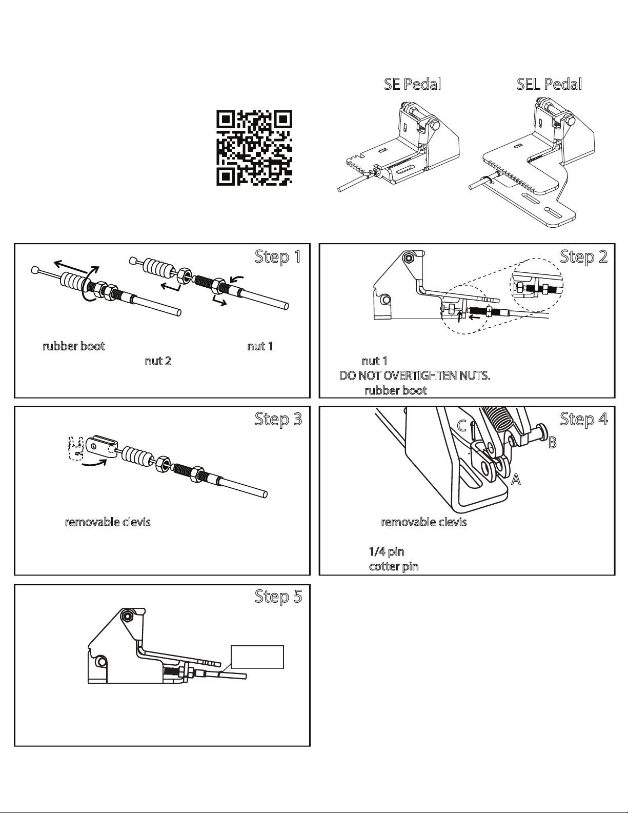
SE Pedal SEL Pedal
Step 4
Step 5
Step 2
Position removable clevis onto cable ball.
Step 1
Pull rubber boot oof cable tting and spin nut 1
oof cable tting. Spin nut 2 onto tting so one
thread is showing.
SE & SEL Pedal Cable Installation
1 thread
Nut 1
Nut 2
For video showing
how to install cable
on pedal scan using
phone camera.
Secure with
cable tie
A) Once pedal is installed on mower attach cable clamp
or zip tie to secure cable.
B) Verify everything is in place and secure.
A) Position removable clevis on pedal with clevis slot
on cut out side of pedal.
B) Insert 1/4 pin with head on same side as clevis slot.
C) Insert cotter pin and wrap around pin to secure.
C
A
B
A) Slip cable wire into slot.
B) Spin nut 1 onto tting to secure cable to pedal.
DO NOT OVERTIGHTEN NUTS.
C) Push rubber boot back onto tting.
Step 3
GrassFlap.com Phone: (502)594-3546 9
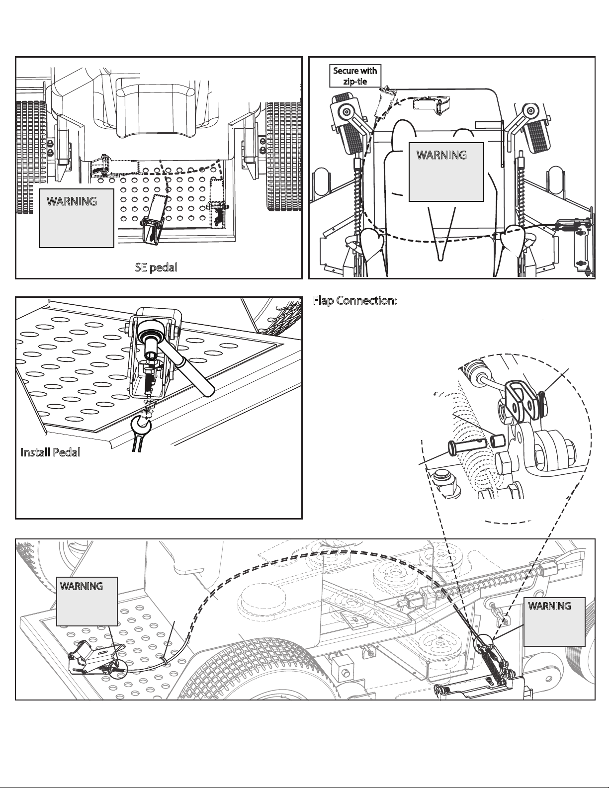
SE Pedal Location & Cable Routing
Option 1
Option 2
Option 3
Preferred locations for SE pedal assembly.
WARNING:
First
½” after
tting must
be straight
SE Pedal Cable Routing
on Stand-On
Tie cable
down
WARNING:
First ½” after
tting must
be straight
WARNING:
First ½” after
tting must
be straight
2x
Install Pedal
A) Mark and drill two 11/32” holes, if needed, for pedal
mounting bolts.
B) Tighten two 5/16” x 1” carriage bolts to secure pedal
assembly to mower deck.
Option 1
Secure with
zip-tie Option 2 SE Pedal Cable Routing
on Zero Turn
WARNING:
First
½” after
tting must
be straight
A
B
C
D
FLAP CONNECTION
3/16”
Clevis Pin
10-99-22
Bushing Cable
Pin Flap End
10-99-28
Flap Connection:
A) Place 1/4”bushing in ap.
B) Slip clevis onto ap.
C) Insert 3/16 pin with head
on spring side.
D) Insert cotter pin and bend
around pin.
Cotter Pin

Cotter Pin
WARNING:
First ½” after
tting must
be straight
WARNING:
First ½” after
tting must
be straight
A
B
C
D
FLAP CONNECTION
3/16”
Clevis Pin
10-99-22
Flap Connection:
A) Place 1/4”bushing in ap.
B) Slip clevis onto ap.
C) Insert 3/16” pin with head
on spring side.
D) Insert cotter pin and bend
around pin.
Bushing Cable
Pin Flap End
10-99-28
Zip Tie Cable
to Pedal
2x
Install Pedal
A) Mark and drill two 11/32” holes, if needed, for pedal
mounting bolts.
B) Tighten two 5/16” x 1” hex bolts to secure pedal
assembly to mower deck.
GrassFlap.com Phone: (502)594-3546 10
SEL Pedal Location & Cable Routing
Preferred location for SEL pedal assembly.
WARNING:
First
½” after
tting must
be straight
Tabla de contenidos
Otros manuales de Accesorios para cortadoras de césped de GrassFlap


