
Graco InvisiPac HM10 Manual de usuario

Instructions
For delivering and dispensing hot melt adhesive pellets. For professional use only.
Not approved for use in explosive atmospheres or hazardous (classified) locations.
1200 psi (8.3 MPa, 83 bar) Maximum Fluid Working Pressure
400°F (204°C) Maximum Fluid Operating Temperature
100 psi (0.7 MPa,7 bar) Maximum Air Inlet Pressure.
Important Safety Instructions
Read all warnings and instructions in this
manual and in the applicator and hose
manuals. Save all instructions.
3A7259C
EN
InvisiPac® HM10 Hot
Melt Delivery System
On-Board Hopper
Models
Remote Vacuum
Feed Models

2 3A7259C
Contents
Models . . . . . . . . . . . . . . . . . . . . . . . . . . . . . . . . . . . . 3
Warnings . . . . . . . . . . . . . . . . . . . . . . . . . . . . . . . . . . 5
Component Identification . . . . . . . . . . . . . . . . . . . . 8
Typical Installation . . . . . . . . . . . . . . . . . . . . . . . . . . 9
Installation. . . . . . . . . . . . . . . . . . . . . . . . . . . . . . . . 11
Grounding . . . . . . . . . . . . . . . . . . . . . . . . . . . . . 11
Location . . . . . . . . . . . . . . . . . . . . . . . . . . . . . . . 11
Drain Before Using. . . . . . . . . . . . . . . . . . . . . . . 11
System Requirements . . . . . . . . . . . . . . . . . . . . 12
Setup Adhesive Supply . . . . . . . . . . . . . . . . . . . 13
Heated Hose and Applicator Connections . . . . 14
Air Supply Installation . . . . . . . . . . . . . . . . . . . . 16
Connect Material Tracking Input . . . . . . . . . . . . 17
Connect Electrical Cord. . . . . . . . . . . . . . . . . . . 18
Set Baseline ADM Settings . . . . . . . . . . . . . . . . 19
Setup . . . . . . . . . . . . . . . . . . . . . . . . . . . . . . . . . . . . 21
Connect PLC Inputs. . . . . . . . . . . . . . . . . . . . . . 21
Wire PLC Outputs . . . . . . . . . . . . . . . . . . . . . . . 24
Operation. . . . . . . . . . . . . . . . . . . . . . . . . . . . . . . . . 26
Operation Overview . . . . . . . . . . . . . . . . . . . . . . 26
Operation Requirements . . . . . . . . . . . . . . . . . . 26
Pressure Relief Procedure . . . . . . . . . . . . . . . . . 26
Initial Startup and Prime Procedure. . . . . . . . . . 26
Dispense Adhesive . . . . . . . . . . . . . . . . . . . . . . 28
Check the Adhesive Fill Rate . . . . . . . . . . . . . . . 28
Shutdown. . . . . . . . . . . . . . . . . . . . . . . . . . . . . . 29
Maintenance . . . . . . . . . . . . . . . . . . . . . . . . . . . . . . 30
Drain the System . . . . . . . . . . . . . . . . . . . . . . . . 30
Flushing Procedure . . . . . . . . . . . . . . . . . . . . . . 31
Inspection Schedule . . . . . . . . . . . . . . . . . . . . . 32
Funnel Maintenance. . . . . . . . . . . . . . . . . . . . . . 32
Pump Filter Maintenance . . . . . . . . . . . . . . . . . . 33
Software Update Procedure . . . . . . . . . . . . . . . 35
ADM Guide . . . . . . . . . . . . . . . . . . . . . . . . . . . . . . . 36
Screen Navigation . . . . . . . . . . . . . . . . . . . . . . . 36
Screen Symbols. . . . . . . . . . . . . . . . . . . . . . . . . 36
Screen Navigation Overview . . . . . . . . . . . . . . . 36
Data Management . . . . . . . . . . . . . . . . . . . . . . . 37
ADM Screens . . . . . . . . . . . . . . . . . . . . . . . . . . . . . 39
Diagnostics Screens . . . . . . . . . . . . . . . . . . . . . 39
Logs Screens . . . . . . . . . . . . . . . . . . . . . . . . . . . 42
Setup Screens . . . . . . . . . . . . . . . . . . . . . . . . . . 43
Advanced Screens. . . . . . . . . . . . . . . . . . . . . . . 45
Communications Gateway Module (CGM) . . . . . . 48
Overview. . . . . . . . . . . . . . . . . . . . . . . . . . . . . . . 48
Available Internal Data . . . . . . . . . . . . . . . . . . . . 48
Automation Outputs . . . . . . . . . . . . . . . . . . . . . . 49
Automation Inputs . . . . . . . . . . . . . . . . . . . . . . . 60
Command Interface . . . . . . . . . . . . . . . . . . . . . . 65
Command Interface Timing Diagram . . . . . . . . . 65
Command Interface Table . . . . . . . . . . . . . . . . . 66
Troubleshooting . . . . . . . . . . . . . . . . . . . . . . . . . . . 71
Melter Pump and Fluid Hose Leak Troubleshooting
. . . . . . . . . . . . . . . . . . . . . . . . . . . . . . . . . . . . . . 71
Fill Rate Troubleshooting and Venturi Air
Adjustment. . . . . . . . . . . . . . . . . . . . . . . . . . 72
Fill System Verification Checklist . . . . . . . . . . . . 73
Power Input Verification Checklist . . . . . . . . . . . 73
Error Codes . . . . . . . . . . . . . . . . . . . . . . . . . . . . . . . 74
Alarms . . . . . . . . . . . . . . . . . . . . . . . . . . . . . . . . 75
Advisories and Deviations . . . . . . . . . . . . . . . . . 79
Repair. . . . . . . . . . . . . . . . . . . . . . . . . . . . . . . . . . . . 82
Prepare Equipment for Service . . . . . . . . . . . . . 82
Remove Equipment Covers . . . . . . . . . . . . . . . . 82
Install Equipment Covers . . . . . . . . . . . . . . . . . . 83
Access the Electrical Enclosure . . . . . . . . . . . . . 83
Install the ADM Screen. . . . . . . . . . . . . . . . . . . . 83
Sensor and Switch Repairs . . . . . . . . . . . . . . . . 84
Melter Sensor Repairs . . . . . . . . . . . . . . . . . . . . 85
Air Control Repairs . . . . . . . . . . . . . . . . . . . . . . . 86
Hopper Repair . . . . . . . . . . . . . . . . . . . . . . . . . . 87
Melter Pump Assembly Repairs . . . . . . . . . . . . . 88
Melter Pump Component Repairs . . . . . . . . . . . 92
Remove Pump Components from the Melter . . 93
Assemble Pump Components . . . . . . . . . . . . . . 96
Heater Repairs . . . . . . . . . . . . . . . . . . . . . . . . . . 98
Electrical Component Repairs . . . . . . . . . . . . . 100
AMZ Wiring Connections . . . . . . . . . . . . . . . . . . . 103
Electrical Schematics. . . . . . . . . . . . . . . . . . . . . . 105
Light Tower Wiring . . . . . . . . . . . . . . . . . . . . . . 107
Pneumatic Schematic . . . . . . . . . . . . . . . . . . . 108
Parts . . . . . . . . . . . . . . . . . . . . . . . . . . . . . . . . . . . . 109
System Structure . . . . . . . . . . . . . . . . . . . . . . . 109
Melter Pump Assembly: 20B911 . . . . . . . . . . . 116
Air Regulator Assembly . . . . . . . . . . . . . . . . . . 118

Models
3A7259C 3
Repair Kits. . . . . . . . . . . . . . . . . . . . . . . . . . . . . . . 119
Hopper Kits . . . . . . . . . . . . . . . . . . . . . . . . . . . 121
Electrical Kits . . . . . . . . . . . . . . . . . . . . . . . . . . 122
Funnel Assembly Kit 20B912 . . . . . . . . . . . . . . 122
Light Tower Kit 20B729 . . . . . . . . . . . . . . . . . . 123
AMZ Circuit Board Replacement Kit 25M525 . 125
Communications Gateway Module and Fieldbus
Kits. . . . . . . . . . . . . . . . . . . . . . . . . . . . . . . 126
Communications Gateway Module (CGM) and
Fieldbus Setup. . . . . . . . . . . . . . . . . . . . . . 127
Installation Kits. . . . . . . . . . . . . . . . . . . . . . . . . 129
Upgrade Kits . . . . . . . . . . . . . . . . . . . . . . . . . . 131
Adapter Kits . . . . . . . . . . . . . . . . . . . . . . . . . . . 135
Dimensions . . . . . . . . . . . . . . . . . . . . . . . . . . . . . . 135
Mounting Hole Dimensions . . . . . . . . . . . . . . . . . 136
Technical Specifications . . . . . . . . . . . . . . . . . . . 138
Graco Standard Warranty . . . . . . . . . . . . . . . . . . 140
Related Manuals
Models
On-Board Hopper Models
Remote Vacuum Feed Models
Models that use a separate drum vacuum feed system.
Purchase separately. See Compatible Drum Vacuum
Feed Systems, page 3.
Compatible Drum Vacuum Feed Systems
Compatible with On-Board Hopper Models. Purchase
feed system separately.
English
Manual Manual Title
334627 InvisiPac GM100 Plug-Free™ Hot Melt
Applicator
3A2805 InvisiPac GS35 Hot Melt™ Applicator
332072 InvisiPac Heated Hose
334784 InvisiPac Pattern Controller
3A3158 InvisiPac Material Tracking Kit
3A4937 InvisiPac Feed System
334629 InvisiPac Advanced Feed System
3A5256 Auto Multi-Zone (AMZ) Repair Kit
312864 Communications Gateway Module
(CGM)
3A9350 InvisiPac CGM Interface
Model Voltage
(VAC) Channels
Maximum
Fluid
Pressure
Maximum
Air Inlet
Pressure
20B715 200-240 2 1200 psi
(8.3 MPa,
83 bar)
100 psi
(0.7 MPa,7
bar)
20B716 200-240 4
20B717 400-480 2
20B718 400-480 4
Model Voltage
(VAC) Channels
Maximum
Fluid
Pressure
Maximum
Air Inlet
Pressure
20B725 200-240 2 1200 psi
(8.3 MPa, 83
bar)
100 psi
(0.7
MPa,7
bar)
20B726 200-240 4
20B727 400-480 2
20B728 400-480 4
Part Description English
Manual
25C193 InvisiPac Feed System
Drum feed system for
standard pellet feed
applications
3A4937
17D749 InvisiPac Advanced Feed
System
Drum feed system for
chiclet feed applications
334629

Models
4 3A7259C
Required Tools
- Standard allen wrench set
- Metric allen wrench set
- Various sizes of crescent wrenches
- 11/16 in. wrench
- 3/8 in. ratchet
- 3/8 in. socket
- 5/16 in. driver
- 7/16 in. socket
- 7/8 in. deep well socket
- 1 in. socket
- 13 mm socket
- 10 mm socket
- 1/2 in. ratchet
- Side cutter
- Phillips head screwdriver
- Flat head screwdriver
- Multimeter
- Tubing cutter
Approvals

Warnings
3A7259C 5
Warnings
The following are general warnings related to the setup, use, grounding, maintenance, and repair of this equipment.
Additional, more specific warnings may be found throughout the body of this manual where applicable. Symbols
that appear in the body of the manual refer to these general warnings. When these symbols appear throughout the
manual, refer back to these pages for a description of the specific hazard.
DANGER
SEVERE ELECTRIC SHOCK HAZARD
This equipment can be powered by more than 240V. Contact with this voltage will cause death or
serious injury.
• Turn off and disconnect all power before disconnecting any cables and before servicing equipment.
• This equipment must be grounded. Connect only to grounded power source.
• All electrical wiring must be done by a qualified electrician and comply with all local codes and
regulations.
WARNING
BURN HAZARD
Equipment surfaces and fluid that is heated can become very hot during operation. To avoid severe
burns:
• Do not touch hot fluid or equipment.
\
SKIN INJECTION HAZARD
High-pressure fluid from dispensing device, hose leaks, or ruptured components will pierce skin. This
may look like just a cut, but it is a serious injury that can result in amputation. Get immediate surgical
treatment.
• Do not point dispensing device at anyone or at any part of the body.
• Do not put your hand over the fluid outlet.
• Do not stop or deflect leaks with your hand, body, glove, or rag.
• Follow the Pressure Relief Procedure when you stop dispensing and before cleaning, checking,
or servicing equipment.
• Tighten all fluid connections before operating the equipment.
• Check hoses and couplings daily. Replace worn or damaged parts immediately.

Warnings
6 3A7259C
FIRE AND EXPLOSION HAZARD
Flammable fumes, such as solvent and paint fumes, in work area can ignite or explode. Solvent
flowing through the equipment can cause static sparking. To help prevent fire and explosion:
• Do not use solvent-based adhesives that can create an explosive atmosphere when processed.
• Use equipment only in well ventilated area.
• Eliminate all ignition sources; such as pilot lights, cigarettes, portable electric lamps, and plastic
drop cloths (potential static sparking).
• Ground all equipment in the work area. See Grounding instructions.
• Never dispense or flush at high pressure
• Keep work area free of debris, including solvent, rags and gasoline.
• Do not plug or unplug power cords, or turn power or light switches on or off when flammable fumes
are present.
• Use only grounded hoses.
•Stop operation immediately if static sparking occurs or you feel a shock. Do not use equipment
until you identify and correct the problem.
• Keep a working fire extinguisher in the work area.
MOVING PARTS HAZARD
Moving parts can pinch, cut or amputate fingers and other body parts.
• Keep clear of moving parts.
• Do not operate equipment with protective guards or covers removed.
• Equipment can start without warning. Before checking, moving, or servicing equipment, follow the
Pressure Relief Procedure and disconnect all power sources.
EQUIPMENT MISUSE HAZARD
Misuse can cause death or serious injury.
• Do not operate the unit when fatigued or under the influence of drugs or alcohol.
• Do not exceed the maximum working pressure or temperature rating of the lowest rated system
component. See Technical Specifications in all equipment manuals.
• Use fluids and solvents that are compatible with equipment wetted parts. See Technical
Specifications in all equipment manuals. Read fluid and solvent manufacturer’s warnings. For
complete information about your material, request Safety Data Sheets (SDSs) from distributor or
retailer.
• Do not leave the work area while equipment is energized or under pressure.
• Turn off all equipment and follow the Pressure Relief Procedure when equipment is not in use.
• Check equipment daily. Repair or replace worn or damaged parts immediately with genuine
manufacturer’s replacement parts only.
• Do not alter or modify equipment. Alterations or modifications may void agency approvals and
create safety hazards.
• Make sure all equipment is rated and approved for the environment in which you are using it.
• Use equipment only for its intended purpose. Call your distributor for information.
• Route hoses and cables away from traffic areas, sharp edges, moving parts, and hot surfaces.
• Do not kink or over bend hoses or use hoses to pull equipment.
• Keep children and animals away from work area.
• Comply with all applicable safety regulations.
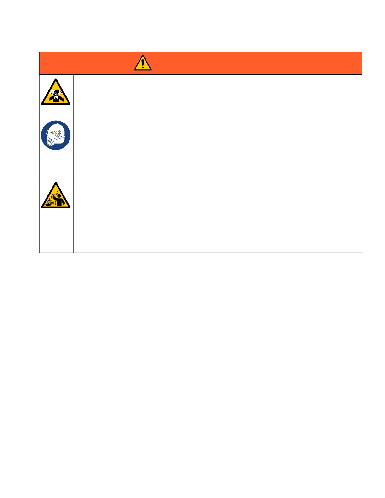
WARNING
Warnings
3A7259C 7
TOXIC FLUID OR FUMES HAZARD
Toxic fluids or fumes can cause serious injury or death if splashed in the eyes or on skin, inhaled, or
swallowed.
• Read Safety Data Sheets (SDSs) to know the specific hazards of the fluids you are using.
• Store hazardous fluid in approved containers, and dispose of it according to applicable guidelines.
PERSONAL PROTECTIVE EQUIPMENT
Wear appropriate protective equipment when in the work area to help prevent serious injury, including
eye injury, hearing loss, inhalation of toxic fumes, and burns. Protective equipment includes but is not
limited to:
• Protective eyewear, and hearing protection.
• Respirators, protective clothing, and gloves as recommended by the fluid and solvent
manufacturer.
PRESSURIZED ALUMINUM PARTS HAZARD
Use of fluids that are incompatible with aluminum in pressurized equipment can cause serious
chemical reaction and equipment rupture. Failure to follow this warning can result in death, serious
injury, or property damage.
• Do not use 1,1,1-trichloroethane, methylene chloride, other halogenated hydrocarbon solvents or
fluids containing such solvents.
• Do not use chlorine bleach.
• Many other fluids may contain chemicals that can react with aluminum. Contact your material
supplier for compatibility.
WARNING

Component Identification
8 3A7259C
Component Identification
6
505
515
229
504
207
205
48
204
256
60
628
202
53
Ref. Description
6 Advanced Display Module (ADM)
204 Main Power Switch
48 Hopper Lid
53 Air Venturi Restrictor
60 System Air Filter with System Air Inlet
202 AMZ Circuit Board Assembly
205 Incoming Power Strain Relief Bushing
207 I/O cable gland
229 Funnel Inlet
504 Pump Air Pressure Gauge
505 Pump Air Pressure Regulator
515 USB Port Cover
256 Electrical Port Covers for Heated Hose
Connection Ports
628 Melter Fluid Outlets Plugs for Heated Hose
Connection
Ref. Description

Typical Installation
3A7259C 9
Typical Installation
The installation shown is only a guide for selecting an installing system components. The components in the typical
installation illustrations are not included with the system.
On-Board Hopper Models Typical Installation
628
256
BB
AA
DD
CC
EE
FF
62
Ref. Description
256‡ Electrical Port Covers for Heated Hose
Connection Ports
628‡ Melter Fluid Outlets Plugs for Heated Hose
Connection
62‡ Bleed-Type Air Valve
AA Applicator
BB Heated Hose
CC Main Air Line
DD Power Cord
EE Applicator Air Line
FF Applicator Electrical Line
‡ Included with the system

Typical Installation
10 3A7259C
Remote Vacuum Feed Models Typical Installation
628
256
BB
AA
DD
CC
EE
FF
62
GG
HH
JJ
Ref. Description
256‡ Electrical Port Covers for Heated Hose
Connection Ports
628‡ Melter Fluid Outlets Plugs for Heated Hose
Connection
62‡ Bleed-Type Air Valve
AA Applicator
BB Heated Hose
CC Main Air Line
DD Power Cord
EE Applicator Air Line
FF Applicator Electrical Line
GG Feed Tube
HH Feed Air Supply Hose
JJ Feed System
‡ Included with the system
Tabla de contenidos
Manuales populares de Accesorios de soldadura de otras marcas


Miller Electric
Miller Electric OM-842 Manual de usuario

Miller
Miller A-200 Series Manual de usuario

Abicor Binzel
Abicor Binzel ABIMIG WT Series Manual de usuario

optrel
optrel lifeflip autopilot Manual de usuario

Miller
Miller MIGmatic M-25 Manual de usuario

Tregaskiss
Tregaskiss TOUGH GUN TT3 Reamer Manual de usuario


