Gigant BG140 Guía de configuración

BG140 barriers
assembly and installation manual
Read this manual carefully before performance of work
The BG140 barrier is delivered partially assembled and is assembled by the customer from the
following elements: double posts, triple posts, crossbars, 75 mm connection strap, 32 mm fixing
pipes, pipes for holes in the wall, decorative rings, post caps, post fixings in crossbars, M8x50
screws, clips, self-tapping anchors.
Figure 1. Double post (1), triple post (2), crossbar for 2500х3000gates (3), crossbar for 3000х3000 gates (4),
75 mm connection strap through the wall (5), fixing pipe 32 mm (6), pipes for holes in the wall (7),
decorative ring (8)
.
1 2
3
4
5
6
7
8

Pass the crossbars through the holes in the upper parts of the posts. The distance from the
end of the crossbar to the axis of the post should be 630 mm (or 560 mm if measured from the
end of the crossbar to the edge of the post) on the side of the gate drive, and on the opposite
side of the gate drive, this distance should be 380 mm (or 310 mm if measured from the end
crossbars to the edge of the post). These dimensions are shown in fig. 3 and fig. 4.
1.
9 10
11 12
13 14
Figure 2. Barrier auxiliary components: cap of the end of the crossbar (9),
post cap (10), post retainer in the crossbar (11), M8x50 screw (12),
clip for caps (13), self-tapping anchor (14).
Caps, clips, fixing pipes, pipes for holes in the wall, cosmetic overlays for holes in the wall are
available separately to ensure the possibility of assembling the barrier.
The barrier design is presented in two versions: for gates with a clearance of 2500x3000 mm and
3000x3000 mm. The posts and the crossbar should overlap the opening of the gate by 100 mm on
each side.
The algorithm for assembling BG140 barrier elements is as follows:
BG140 barriers
assembly and installation manual

Drill holes in the wall according to the dimensions shown in fig. 3 and fig. 4. The height of the
axes of the holes above the floor should be 2955 mm, the distance from the gate opening to
the axis of the hole on the side of the gate drive is 500 mm, the distance from the gate opening
to the axis of the hole on the opposite side from the gate drive is 250 mm. The diameter of the
hole in the wall should be slightly larger than the diameter of the pipe for the holes in the wall
(Fig. 1(7)). The gap between this pipe and the wall will be filled with construction foam.
2.
Figure 3. Key dimensions of the assembled BG140
for protection of 3000x3000 mm gates.
Install the pipes (Fig. 1(7)) into the holes in the wall with mounting foam (view B in Fig. 4 and
Fig. 5).
3.
BG140 barriers
assembly and installation manual

Install 75 mm connection straps in accordance with the algorithm indicated in fig. 7.
Figure 4. Key dimensions of the assembled BG140
for protection of 2500х3000 mm gates.
Place the structure assembled in point 1 approximately in the place of installation (see Fig.
7.a).
Paste cosmetic rings (Fig. 1(8)) on the holes in the wall as shown in Fig. 5 and fig. 7-b.
Pass 75 mm connection straps through the hole in the wall and cosmetic rings (see Fig. 7-
c).
Wedge the 75 mm connection straps (Fig. 1(6)) in the crossbars of the barrier with 32 mm
fixing pipes as shown in Fig. 7-d.
Close the ends of the barrier crossbars with caps (Fig. 2(9)) as shown in Fig. 7. e.
Fix each cap with a pair of clips (Fig. 2.13), as shown in Fig. 7-f and in fig. 9. To install the
clips, drill 2 holes with a diameter of 7 mm at a distance of 20 mm from the end of the
crossbar pipe upon cap installation. Insert clips into these holes.
4.1.
4.2.
4.3.
4.4.
4.5.
4.6.
BG140 barriers
assembly and installation manual

6.Fix the tops of the posts to the connection straps.
Insert the post retainer in the crossbar at the top of the pole (Fig. 2.11) as shown in Fig. 8.a
- 8.b.
Drill the crossbar through the hole in the post retainer with a 6 mm-diameter drill to a depth
of 60 mm.
Screw the M8x30 screw into the hole (Fig. 8.c).
Insert the post caps (Fig. 2.10) as shown in (Fig. 8.d).
Drill 7 mm holes at a distance of 20 mm from the end of the pillar (Fig. 8.d) and hammer
the clips.
6.1.
6.2.
6.3.
6.4.
6.5.
Check and, if necessary, adjust the position of the barrier posts in space. Check the conformity
of the dimensions indicated in fig. 3 and fig. 4.
5.
Figure 5. Cross-section of the assembled barrier structure.
BG140 barriers
assembly and installation manual
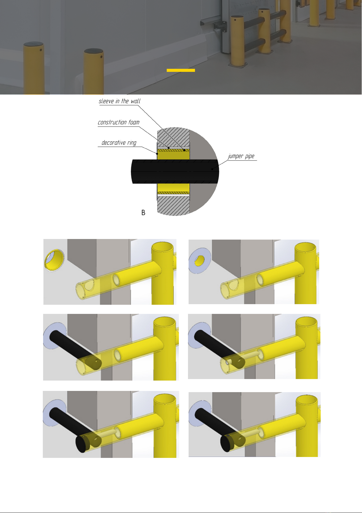
Figure 6. Cross-section of a wall with a connection strap.
a b
Figure 7. Installation of a 75 mm connection strap.
c d
e f
BG140 barriers
assembly and installation manual

аb c
Figure 9. Installation and fixation of caps.
Figure 8. Fixing the top of the post to the connection strap and installing of the cap.
d e
BG140 barriers
assembly and installation manual

After assembly, the barrier must be fixed to the foundation with self-tapping anchors, which are
supplied complete with it. Before drilling holes in the floor, it is necessary to check the
parallelism of the one-meter posts to the central three-meter post (in case of the correct mutual
placement, the gap between adjacent poles is 60 mm along the entire height). To mark the
holes, it is recommended to use the holes in the metal supports of the barrier as templates.
Drilling should be performed with a 10 mm drill bit to a depth of at least 100 mm (Fig. 10.1). If
larger diameter drill bits are used, the anchor will lose its efficiency during the barrier service.
Drilling products must be removed from the holes in the foundation (Fig. 10.2). The properly
installed self-tapping anchor will screw in tightly, so it is recommended to use an impact wrench
with a flexible shaft (Fig. 10.3 and 10.4). The impact wrench for screwing the self-tapping
anchors which are supplied as component parts must provide a torque of 950 Nm and higher.
7.
Figure 10. Barrier fixing.
MODERN SOLUTIONS FOR YOUR COMPANY
BG140 barriers
assembly and installation manual
Tabla de contenidos
Otros manuales de Columna elevadora de Gigant


