GEZE GCLR-O 2000 Manual de usuario

EN Manual
GCLR-I 2000/
GCLR-O 2000
GEZE Wide-range Reader
Indoor/Outdoor
153069-01

GCLR-I 2000/GCLR-O 2000
2
Contents
Symbols and illustrations.................................................................................3
Revisions and validity........................................................................................3
Product liability....................................................................................................3
About this document ........................................................................................3
1 Safety notices...........................................................................................4
1.1 Intended use ............................................................................................4
1.2 General information .............................................................................4
1.3 Notes about installation ......................................................................4
1.4 Notes on routing the cables...............................................................4
1.5 Danger of electric shock .....................................................................4
2 Product description...............................................................................5
3 Brief instructions.....................................................................................6
4 Installation and commissioning........................................................6
4.1 Step 1: Install reader GCLR 2000 .......................................................6
4.2 Step 2: Connect the reader .............................................................. 10
4.3 Step 3: Teach/delete transponders ............................................... 12
4.4 Overview DIP switches...................................................................... 13
4.5 Transponders ........................................................................................ 15
4.6 LED display on the GCLR housing ................................................. 17
5 Conguration program – wide-range reader GCLR 2000..... 18
5.1 Installing the conguration program........................................... 18
5.2 Main menu............................................................................................. 18
5.3 Setting up a connection with the GCLR 2000........................... 23
6 "Networked operation" mode of operation............................... 24
7 Wiring diagrams................................................................................... 28
7.1 Accompany function with automatic drives without emer-
gency exit function............................................................................. 28
7.2 Accompany function in escape and rescue routes with door
control unit TZ 320.............................................................................. 30
7.3 Control..................................................................................................... 32
8 Technical data....................................................................................... 33
9 Transponder list ................................................................................... 35

3
GCLR-I 2000/GCLR-O 2000
Symbols and illustrations
Important information and technical notes are highlighted to explain cor-
rect operation.
Symbol Meaning
means "Important Information";
information to prevent property damage, to understand or optimise
the operation sequences
means "additional information"
XSymbol for an action: there is something you must do here.
XIf there are several actions to be taken, keep to the given order.
Revisions and validity
Valid from software version 22.14
Product liability
àIn compliance with the liability of the manufacturer for his products as
dened in the German "Product Liability Act", the information contained
in this brochure (product information and intended use, misuse, product
performance, product maintenance, obligations to provide information
and instructions) must be observed. Non-observance releases the manu-
facturer from his liability.
àIf unauthorised changes are made to the components, GEZE cannot be
made liable in any way whatsoever for any resulting damages.
àUse only spare parts and accessories approved by the manufacturer.
àOnly modications approved by the manufacturer may be carried out on
the device.
About this document
This document describes the connection, commissioning and functions of
the wide-range reader GCLR 2000 for standard applications.
More detailed settings and functions, which are necessary mainly in net-
worked operation, are described in separate documents.

Safety notices GCLR-I 2000/GCLR-O 2000
4
1 Safety notices
To ensure personal safety, it is important to follow these safety instructions.
These instructions must be kept.
1.1 Intended use
àThe components are intended for access control applications.
àThe wall-mounted reader must be used in the specied area.
àAny other use than the intended use as well as all changes to the product
are not permissible.
1.2 General information
àRead the safety notices thoroughly and with care before putting the
device into operation.
àKeep this document is a safe place.
àObserve the country-specic standards and regulations.
1.3 Notes about installation
àDo not operate the device near electro-magnetic radiation.
àThe device may only be installed on a rm base.
àThe connection to the mains voltage must be made by a professional
electrician.
XThe power connection and safety earth conductor test must be carried
out in accordance with DIN VDE 0100-610.
1.4 Notes on routing the cables
àRoute cables as shown in the GEZE cable plan.
àDene the installation position of the reader in advance.
àPreliminary cable routing may not be necessary in connection with
automatic drives. If the voltage supply to the reader is possible via an
automatic drive installed nearby, the cable must not necessary be routed
beforehand and can be routed on the surface during installation.
1.5 Danger of electric shock
àThe connection to the mains voltage must be made by a professional
electrician.
àThe power connection and safety earth conductor test must be carried
out in accordance with DIN VDE 0100-610.
àCheck cables before installation to make sure they are voltage-free.
àObserve standards VDE 0100 and VDE 0815 for cable routing.
àOnly operate the device with the designated operating voltage.
àMake sure that the supply circuit has an easily accessible circuit breaker.

5
Product descriptionGCLR-I 2000/GCLR-O 2000
2 Product description
Authorisations can be issued without contact at a distance of up to 3.8m
using the GEZE wide-range reader.
Usage options
àAutomatic door drives such as GEZE sliding door drives, swing door
drives or automatic gates can be opened for barrier-free access when the
door/gate is approached.
àThe integrated wireless technology assigns authorisations via radio trans-
mitter when a key is pressed from up to 50m.
àThe "accompany" function prevents people in need of special protection
leaving areas they should not leave on their own for their own safety.
In this case, doors lock automatically or cannot be opened if a person in
need of special protection approaches the door. It can still be passed by
personnel however.
Operating modes
2 operating modes are possible with the wide-range reader:
àStand-alone operation: No further components are required. The tran-
sponders are taught and managed directly at the reader. The door is
activated via the outputs on the reader.
àNetworked operation: The reader is connected to the GEZE access control
system Individual Line. The transponders and the authorisations are man-
aged via the user interface of the web-based control GCMU 524 in this
case. Activation of the door is not via the wide-range reader but rather
via the components of the GEZE Individual Line.
Transponders
There are dierent transponders available for issuing authorisations:
àStandard transponders which are worn by people.
àWrist transponders which can optionally be worn using special safety
bracelets which cannot be removed.
àTransponders with keys for use of the wireless technology.

Brief instructions GCLR-I 2000/GCLR-O 2000
6
3 Brief instructions
For installation and commissioning of the GCLR 2000 in stand-alone opera-
tion.
Step 1: Install the reader (see Chapter 4.1)
XHeed the range of the LF scanned eld when positioning the reader.
XAdjust the range of the LF scanned eld using the rotary potentiometer
"Dist" on the GCLR.
Step 2: Connect the reader (see Chapter 4.2)
XConnect a 12–36VDC voltage supply to the GCLR.
XPreferably, voltage from automatic drives should be used.
XHeed the overall current consumption.
XConnect output "Relay 1" to the peripherals to be activated.
Step 3: Teach the transponders (see Chapter 4.3)
XTeach the transponders using group button 1 in order to thus switch the
output "Relay 1".
4 Installation and commissioning.
4.1 Step 1: Install reader GCLR 2000
During installation, please heed the following:
XChoose the position of the reader in such a way that the LF scanned eld
produced covers the required area.
The GCLR-I 2000 is suitable for installation indoors, the GCLR-O 2000 for
installation outdoors.

7
Installation and commissioning.GCLR-I 2000/GCLR-O 2000
4.1.1 The LF scanned eld
The LF scanned eld spreads spherically around the reader.
The radius r can be adjusted to between 0.5m and 3.8m with the aid of a
rotary potentiometer.
LF scanned eld, view from the front
LF scanned eld, view from above
4.1.2 Adjusting the LF scanned eld
Adjust the range of the scanned eld (LF eld) using the rotary potentio-
meter DIST on the reader board.

Installation and commissioning. GCLR-I 2000/GCLR-O 2000
8
4.1.3 Checking the LF scanned eld
àUsing the eld tester:
The LF scanned eld can be checked using the eld tester.
Flashing LEDs indicate the eld coverage.
àUsing the transponder with 2 keys:
The transponder with 2 keys displays the scanned eld through a red
LED.
àUsing the LEDs on the housing (optional):
When a transponder has been taught, the green LED ashes as soon as
the transponder is within the scanned eld. If a transponder has not been
taught, the green LED goes out as long as the transponder is within the
scanned eld.
4.1.4 Cable routing
XHeed the wiring diagrams and installation instructions of the respective
products.
àThe power supply NT is not required when the voltage supply to the
GCLR is via the drive.
XHeed the overall current consumption.
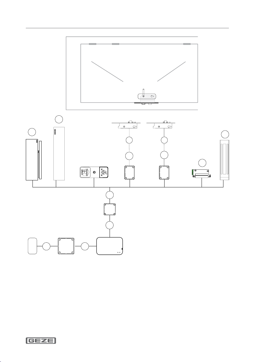
9
Installation and commissioning.GCLR-I 2000/GCLR-O 2000
1 NYM-J 3 × 1.5 mm2
5 J-Y (ST) Y 2 × 2 × 0.8 mm2
7 J-Y (ST) Y 4 × 2 × 0.8 mm2
X Supplied by GEZE:
IQ lock 10 m LiYY 12×0.14 m
– Empty pipe inside-Ø 10 mm
a GEZE swing door drives
b GEZE sliding door drives
c Electric strike
d Holding magnet

Installation and commissioning. GCLR-I 2000/GCLR-O 2000
10
4.2 Step 2: Connect the reader
Transponders are taught using group button 1 on the GCLR. Activation
of the door is via relay1 of the GCLR through the respective input of the
connected peripherals. Other products not shown here can be connected to
relay1 of the GCLR in the same way. Relay1 switches as long as the
transponder is within the set scanned eld + 2 seconds.
Option 1: Transponders which switch relay2 can be taught using group
button 2. A transponder can also be taught in both groups.
The 2nd relay can be used either to realise the "accompany"
function or to activate a 2nd door.
Option 2: If DIP switch 4 is set to "ON", the relay only switches once for 2
seconds when the transponder is detected.
Option 3: If DIP switch 1 is set to "ON", an acoustic buzzer is enabled. This
sounds for the transponders taught in group 1 parallel to the
switching time of relay1.
XHeed the wiring diagrams and installation instructions of the respective
products.
àThe power supply NT is not required when the voltage supply to the
GCLR is via the drive.
XHeed the overall current consumption.
Este manual sirve para los siguientes modelos
1
Tabla de contenidos


