www.gemu-group.com 5 / 22 GEMÜ 4241
Symbol Meaning
Danger of explosion!
Danger of explosion
2 Safety information
The safety information in this document refers only to an indi-
vidual product. Potentially dangerous conditions can arise in
combination with other plant components, which need to be
considered on the basis of a risk analysis. The operator is re-
sponsible for the production of the risk analysis and for com-
pliance with the resulting precautionary measures and re-
gional safety regulations.
The document contains fundamental safety information that
must be observed during commissioning, operation and main-
tenance. Non-compliance with these instructions may cause:
- Personal hazard due to electrical, mechanical and chemical
effects.
- Hazard to nearby equipment.
- Failure of important functions.
- Hazard to the environment due to the leakage of dangerous
substances.
The safety information does not take into account:
- Unexpected incidents and events, which may occur during
installation, operation and maintenance.
- Local safety regulations which must be adhered to by the
operator and by any additional installation personnel.
Prior to commissioning:
1. Transport and store the product correctly.
2. Do not paint the bolts and plastic parts of the product.
3. Carry out installation and commissioning using trained
personnel.
4. Provide adequate training for installation and operating
personnel.
5. Ensure that the contents of the document have been fully
understood by the responsible personnel.
6. Define the areas of responsibility.
7. Observe the safety data sheets.
8. Observe the safety regulations for the media used.
During operation:
9. Keep this document available at the place of use.
10. Observe the safety information.
11. Operate the product in accordance with this document.
12. Operate the product in accordance with the specifications.
13. Maintain the product correctly.
14. Do not carry out any maintenance work and repairs not de-
scribed in this document without consulting the manufac-
turer first.
In cases of uncertainty:
15. Consult the nearest GEMÜ sales office.
3 Product description
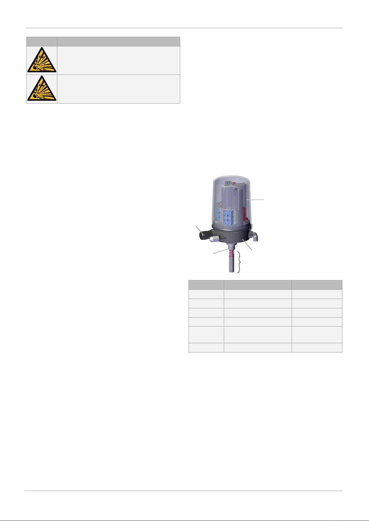
3.1 Construction
Item Name Materials
1 Housing cover PC
2 Housing base PPS
3 Electrical connection SS, PP
4 Adapter piece SS
5 Mounting kit, valve spe-
cific
SS, PP
Seals NBR
3.2 Description
The GEMÜ 4241 combi switchbox is suitable for mounting to
pneumatically operated linear actuators. The position of the
valve spindle is reliably electronically detected and fed back
via the play-free and non-positive mounting by means of a 2-
wire proximity switch (NAMUR). Integrated pilot valves enable
direct activation of the process valve connected to them.
3.3 Function
The GEMÜ 4241 combi switchbox indicates the current posi-
tion of the valve. When the valve is opened, the spindle in the
combi switchbox moves upwards and indicates that the valve
is OPEN using the communication interface. When the valve is
closed, the spring in the mounting kit presses the spindle in
the combi switchbox downwards and indicates that the valve
is CLOSED using the communication interface.
3 Product description