GH10TA USER MANUAL PAGE 2
Issue I July 2017
TABLE OF CO TE TS
1. I TRODUCTIO ............................................................................................................................ 3
1.1. G
RAPHIC SYMBOLS
................................................................................................................................ 3
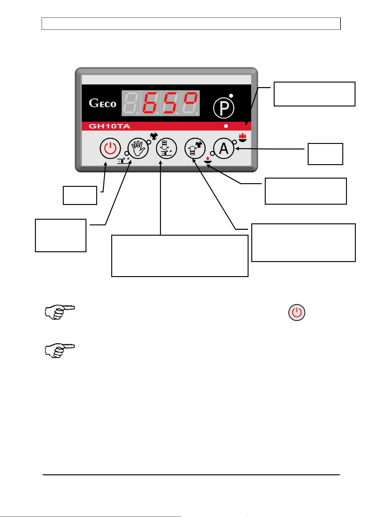
1.2. K
EYBOARD AND
F
UNCTION
K
EYS
............................................................................................................. 4
2. GE ERAL FEATURES ...................................................................................................................... 5
3. TECH ICAL DATA .......................................................................................................................... 6
4. ELECTRICAL SYSTEM A D CO ECTIO RULES .............................................................................. 6
5. QUICK START ................................................................................................................................ 7
6. THE GH10TA OPERATIO ............................................................................................................. 9
6.1. O
PERATED
H
EATING
S
YSTEM
.................................................................................................................. 9
6.2. A
UTOMATIC OPERATION MODE
. ............................................................................................................ 10
6.3. M
ANUAL
O
PERATION
M
ODE
................................................................................................................ 11
6.4. V
IEWING
T
EMPERATURES
..................................................................................................................... 11
6. . A
LARM
C
ONDITIONS
........................................................................................................................... 12
6.6. P
OWER
F
AILURE
................................................................................................................................. 12
6.7. B
OILER
B
URNOUT
D
ETECTION
............................................................................................................... 13
6.8. M
AXIMUM
F
EEDER
T
EMPERATURE
D
ETECTION
........................................................................................ 13
7. USER SETTI GS ........................................................................................................................... 14
7.1. B
OILER
T
EMPERATURE
S
ETTING
(U0) ..................................................................................................... 14
7.2. F
EEDER
S
TANDSTILL
D
URATION
(U1) ..................................................................................................... 14
7.3. M
AINTAIN
P
ERIOD
(U2) ...................................................................................................................... 14
7.4. F
AN SPEED
(U3) ................................................................................................................................. 1
7. . HUW/
R
ETURN
T
EMPERATURE
S
ETTING
(U4) ........................................................................................ 1
7.6. A
NTI
-L
EGIONELLA
F
UNCTION
(U ) ........................................................................................................ 1
8. OPERATI G THE HUW BOILER ..................................................................................................... 15
8.1. I
NSTALATION AND
C
ONNECTIONS
.......................................................................................................... 16
8.2. C
ONFIGURATION OF
A
DDITIONAL
P
UMP
................................................................................................. 16
8.3. HUW
P
RIORITY
.................................................................................................................................. 17
8.4. S
UMMER
M
ODE
................................................................................................................................. 17
9. ROOM THERMOSTAT .................................................................................................................. 17
10. TEMPERATURE LIMITER (STB) ...................................................................................................... 18
11. CO ECTIO DEVICES TO THE GH10TA CO TROLLER .................................................................. 18
12. I FORMATIO O LABELLI G A D COLLECTIO OF WOR OUT ELECTRICAL A D ELECTRO IC
EQUIPME T ................................................................................................................................ 19