
Full Speed Ahead K-Force WE Manual

USER’S MANUAL AND INSTRUCTIONS


Index
1. Introduction
2. Drivetrain Parts
3. Tools and Supplies
4. Frame Preparation
4.1.RD Cable Routing
4.2.FD Cable Routing
4.3.Bottom Bracket Mounting
5. Drivetrain Installation
5.1.FD Installation
5.2.RD Installation
5.3.Shifter Installation
5.4.Battery Installation
5.5.Chain Installation
6. Pairing
7. Usage and Adjustments
7.1.Power ON
7.2.Power OFF
7.3.Rear Derailleur Alignment
7.4.Front Derailleur Alignment
7.5.Limit Screw Adjustment
7.6.B-tension Screw Adjustment
8. Battery Diagnostic
8.1.Main Battery
8.2.Shifter Battery
9. Battery Charging
9.1.Shifter Battery Replacement
10. Diagnostics
11. Battery Warning
12. Important Information

1. Introduction
Congratulations on your Full Speed Ahead product. Please read these instructions and follow them for correct
use. Failure to follow the warnings and instructions could result in damage to product not covered under
warranty, damage to bicycle; or cause an accident resulting in injury or death. Since specific tools and
experience are necessary for proper installation, it is recommended that the product be installed by a qualied
bicycle technician. FSA assumes no responsibility for damages or injury related to improperly installed
components.
2. Drivetrain Parts
FSA K-Force WE is an electronic hybrid drivetrain. It is dened as hybrid because is not completely wireless.
Indeed, there are no wires from shifters to derailleurs but the communication between the two derailleurs is
still effectuated using wires.
The different parts of the drivetrain will be explained in this section.
•Main Battery
The main battery is placed into
the seatpost and provides power
to the two derailleurs through
two wires.
•Shifters
Shifters wirelessly communicate
with derailleurs. They have their
own coin cell batteries, located
inside the housing.
•Wires
Two internally routed wires,
one longer and one shorter,
connect front and rear
derailleurs to the battery.
•Front and Rear Derailleur

3. Tools and Supplies
FSA recommends installation of WE Drivetrain to be performed by a highly experienced bicycle mechanic.
The following tools and supplies are needed for correct installation
of FSA WE Drivetrain. See tool list below:
• Hex wrench sizes (1.5 mm, 2 mm, 5 mm)
• Torque wrench (2-14 Nm range)
• Phillips screwdriver size PH2
• FSA cable guide tool
• 11sp compatible chain rivet tool
• Light grease
FSA recommends using the following protective equipment for
your own safety:
• Protective glasses
• Latex or Nitrile gloves
4. Frame Preparation
Before to start assembling the drivetrain you will have to insert the wires for Front Derailleur FD and Rear
Derailleur RD inside your frame. Any frame compatible with DI2 internal wire specication will be compatible
also for WE wire routing.
RD Wire Routing
Insert the wire guide tool in the rear chainstay to the BB shell as per picture below
Connect the RD wire to the female plug
of the wire guide tool.
Unplug the wire guide and slide it inside
the seat tube from the BB shell as per
picture below.
Pull the wire guide to thread the RD wire
inside the rear chainstay
Connect the wire to the wire guide tool
and pull up through the seat tube.

Slide the wire guide tool through the FD
routing hole into the seat tube.
Connect the FD wire and pull up through
the seat tube.
Bottom Bracket and Crankset mounting
For BB and crankset mounting, check the dedicated FSA instructions.
5. Drivetrain Installation
Before assembling the drivetrain, install Front Derailleur (FD) and Rear Derailleur (RD) wires. WE wires are
compatible with industry standard internal wire routing.
FD Installation
Install the front derailleur on frame
braze-on using supplied.
Adjust the derailleur height so the
gap between outer cage and large
chainring is 1 to 3 mm. See image
3
End of sentence in point 1. Snug
the bolt enough to hold derailleur
in position.
When gap is set, rotate the
derailleur so the cage position is
parallel with the chainrings. See
image 4
When derailleur position is correct,
tighten the derailleur bolt to 5-7
Nm.
123
4 5
FD Wire Routing

RD Installation
Apply a small amount of grease on
the derailleur hanger threads
Rear derailleur must not be forced out of position during installation. Install RD in it set position.
Avoid interference between pulleys or B-tension screw and the dropout during installation.
Using a 5 mm hex wrench, screw
the derailleur in to the hanger.
Tighten the derailleur bolt to 5-7
Nm.
12
Shifters Installation
Install the shifter on the handlebar as shown
in image 1. Position the shifter according to
preference.
Install the brake cable and housing.
Roll the shifter hood forward to expose the shifter
clamp bolt. Tighten the bolt with a 5 mm hex
wrench to 6-8 Nm.
Adjust the lever reach using a 2mm hex wrench,
as shown in image.

Battery Installation
Insert battery in the battery
adaptor.
Plug the derailleur wires in to the
battery terminal leads. Either lead
can work for either wire.
Fully insert the battery and adaptor
in the seatpost and check that it is
secure.
123
Chain Installation
Follow below instruction depending on which cage you use on rear derailleur.
Using short cage
To adjust chain length, use the following procedure if your rear derailleur is mounted with short cage.
1. Install the chain around the big chainring and smallest cog. Route it through rear derailleur cage.
2. In this position, bring the two ends of the chain together until the derailleur cage is vertical.
This is the correct chain length.
3. Use a chain tool to cut the chain to the correct length
Using long cage
To adjust chain length, use the following procedure if your rear derailleur is mounted with long cage.
1. Install the chain around the big chainring and the biggest cog.
2. Pull the chain tight over these two cogs and add one full link (one outer and one inner).
This is the correct chain length.
3. Use a chain tool to cut the chain to the correct length.
Chain lock
If it has not already be done, route the chain through rear derailleur cage.
Follow below operating list for install the Drive Link and lock the chain
1. Insert the plates of the Drive Link on opposing sides of each chain end. (Fig.1) Insert and hook Drive
Link pins into the opposite plate. (Fig.2)
2. To snap Drive Link in locked position, rotate crank until Drive Link is above the chainstay. Hold the rear
brake and rmly push the crank forward. (Fig.3)
Make sure Drive Link snaps in to locked position before use.

To unlock the chain for replacement or other operation, follow below instructions:
1. To disconnect the Drive link, isolate the link. (Fig.4)
2. Firmly squeeze the link bushings together so that the pins and plates decouple. (Fig.5)
3. Pull the plates apart. (Fig.6)
Drive Link cannot be reused if removed. Use a new Drive Link to reassemble.
6. Pairing
Follow the procedure below for new shifter pairing:
With the drivetrain on, push the SET button until
both LEDs illuminate green –the system is now in
SET mode.
Roll the shifter hood forward to expose the
transmitter cover.
To put the shifter in pairing mode push and hold
the pairing switch and simultaneously push either
shifter button.
When the shifter enters pairing mode, the pairing
button will illuminate red.
1 2
3 4
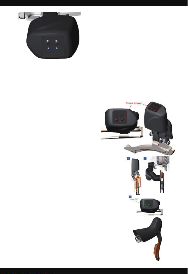
With the shifter in SET mode, press the Power
button on the FD until both the LEDs illuminate
blue.
When pairing is complete, the red LED on the
shifter will blink and turn off. The pairing is
complete.
Repeat the procedure for the other shifter.
5
6
7
7. Usage and Adjustments
Power On
Push and hold the power button. The LED lights will blink
red-blue. When the LED lights ash blue, WE is on.
Release the power button. Push each shift button once to
activate them.
Power Off
Push and hold the power button. The LED lights will blink
blue-red. When the LED lights ash red, WE is off.
WE will also go in to Stand-By mode, and turn off
automatically after a period of inactivity. Those intervals
are customizable in the WE Dashboard Software.
Rear Derailleur Alignment
1. Shift the chain to the small chairing.
2. Shift the rear derailleur to the center (6th) cog.
3. Enter set mode by pushing and holding the SET button
for 2 seconds. Both LEDs will blink green.
4. Press rear shifter button to enter the rear derailleur
adjustment mode (by factory default is the right one but
you can change it in the WE Dashboard Software.)
In this mode, the rear derailleur will operate in micro-
steps.
5. Set the rear derailleur zero position:
a. Rotate the crank and micro-shift the rear derailleur
up until the chain begins to rub on the next cog.
b. Move the RD three micro-steps back.
c. Double check the alignment — The upper jockey
pulley on the rear derailleur should be in line with the
center cog.
6. Exit set mode---push and hold the SET button for 2
seconds. The green light will stop blinking and the rear
derailleur zero position will be saved.
Tabla de contenidos
Manuales populares de Accesorios para bicicletas de otras marcas

Sigma
Sigma BC 16.16 Manual de usuario

Playcore
Playcore Dero Setbacks Manual de usuario

VDO Cyclecomputing
VDO Cyclecomputing x3dw Manual de usuario

Cateye
Cateye RAPID X2 Manual de usuario

buratti meccanica
buratti meccanica Clorofilla Trail Manual de usuario

Shimano
Shimano SG-8R20 Instrucciones de funcionamiento


