Shenzhen Friendcom Technology Development Co., Ltd.
6
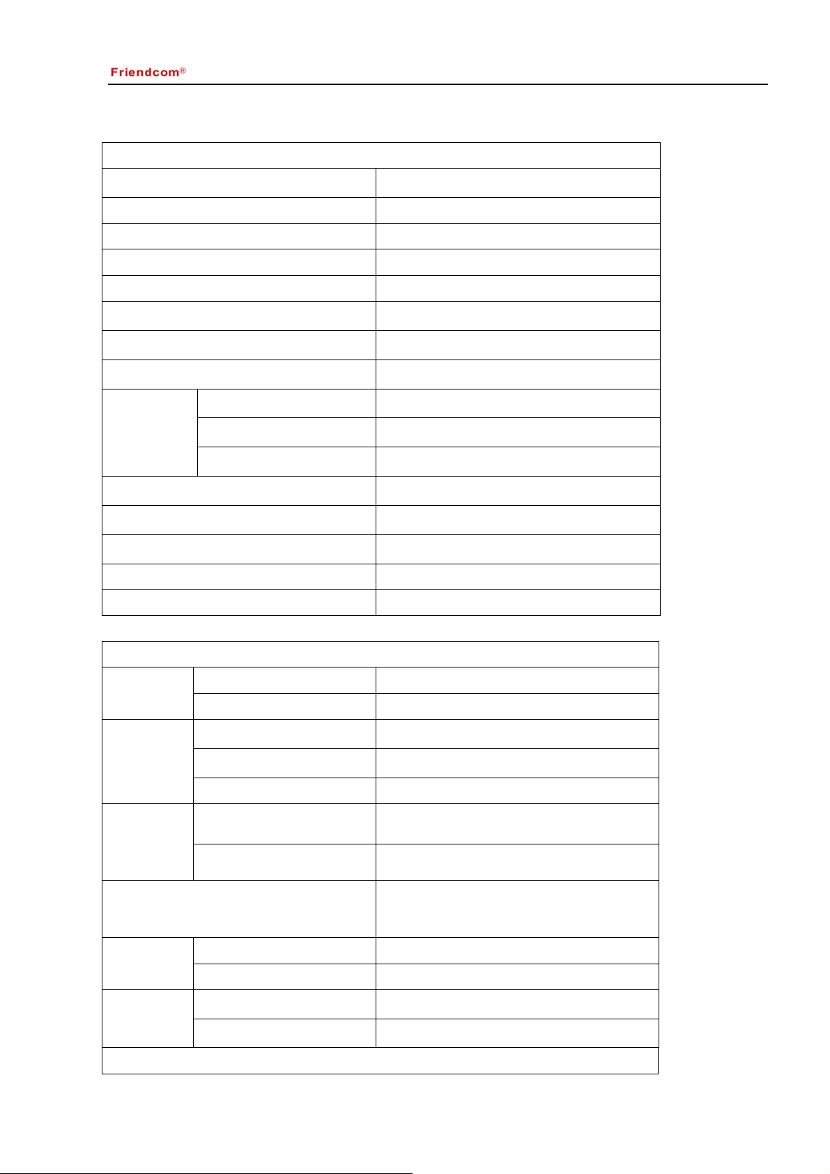
Table 2
Pin Name Pin No.
On DB9
Pin No. on
DB15 Description Remark
AUDIO_IN
(MOD IN)
1 1
Audio input. 3Khz LPF; Modulation
sensitivity is 100mW
AUDIO_IN is effective only when
PIN 7(MIC) is vacant or with +5V
high level. 3KHz LPF filter existed
in audio channel.
AUDIO_OUT
(AF OUT)
2 2
Audio output; 3Khz LPF; Output level at
60% frequency deviation is 100±30mV. This
line has an internal pull-up resistor to +5V.
PTT 3 3
TX control,active low, only when PTT is
active AUDIO_IN and MIC IN are effective.
This line has an internal pull-up to 5V.
GND 4 4
Ground
B+(9.6~16V
DC)
5 5
Positive pole input from DC power; +12V
BUSY 6 6
Logical level output to indicated whether a
carrier or not. Low lever = carrier , high
level=no carrier. This line has a pull-up to
+5V.
Also able to work as simulated
serial port for parameter setting.
MIC IN 7 7
Microphones input. Can directly connect to electrets
MIC, the DC voltage of this pin
should lower than 3.5V, then MIC
transmission can be activated.
SWITCH 8 8
Control output, 5V high level output when
active
Also able to work as simulated
serial port for parameter setting.
SPK 9 9
Audio output from the audio amplifier, @ 8ΩSPK is effective when Pin 7
connect to MIC or GND,(MIC PIN
power than 3.5V
TXD
(Radio)
- 10
The serial data is output from this pin, used
for radio parameter setting,5V TTL
Signal is output from radio.
RXD
(Radio)
- 11
The serial data is input to this pin, used for
radio parameter setting,5V TTL
Signal is input into radio
CH1 - 12
Select channel by Dip switch; the low bit of
4-bit binary code.
Available when channel control
mode is programmed as “by Dip
switch”
CH2 - 13
Select channel by Dip switch; the second bit
of 4-bit binary code.
CH3 - 14
Select channel by Dip switch; the third bit of
4-bit binary code.
CH4 - 15
Select channel by Dip switch; the forth bit of
4-bit binary code.
4 Application Instruction
Functions of PC Personal Computer) software, hereafter called “FC-302 QuickSet v0.1.12 ”, will be illustrated.
Main goal of this instruction is to save time for user by supporting exact usage of the software, at the same time,
give a help to user who wants to utilize the radio for another applications. This programming software enables
the various parameters of FC-302 to be read, modified, programmed and printed.
4.1 Hardware Installation
To apply PC software to radio application, FC-302 QuickSet En v0.1.12, programming cable, programming kit
and PC are needed. In this chapter, instruction for connection of the equipment will be illustrated.