Franklin Fueling Systems Healy 8701VV Manual de usuario

6-1
CARB Approved IOM 6 - Healy Breakaway Model 8701VV - Executive Orders VR-201 and VR-202
Healy Model 8701VV Breakaway
35 to 70 foot pounds. Be sure the vapor tube fitting slides easily into
item 2 before final tightening.
install the secondary hose and tighten to 35 to 70 foot pounds. Be sure
the vapor tube fitting slides easily into item 3 before final tightening.

6-2
CARB Approved IOM 6 - Healy Breakaway Model 8701VV - Executive Orders VR-201 and VR-202
I. HEALY BREAKAWAY RECONNECTION CLAMP
TOOLS NEEDED:
• Healy Breakaway Reconnection Clamp, Part No. 795
• 8mm Hex Head Socket
• Torque wrench
• Safety glasses
RECONNECTION PROCEDURE
1. Inspect each half of the separated breakaway for obvious damage to the outer-shell, plastic
inserts or o-rings; including cracks, chips or tears that may effect reconnecting the two halves.
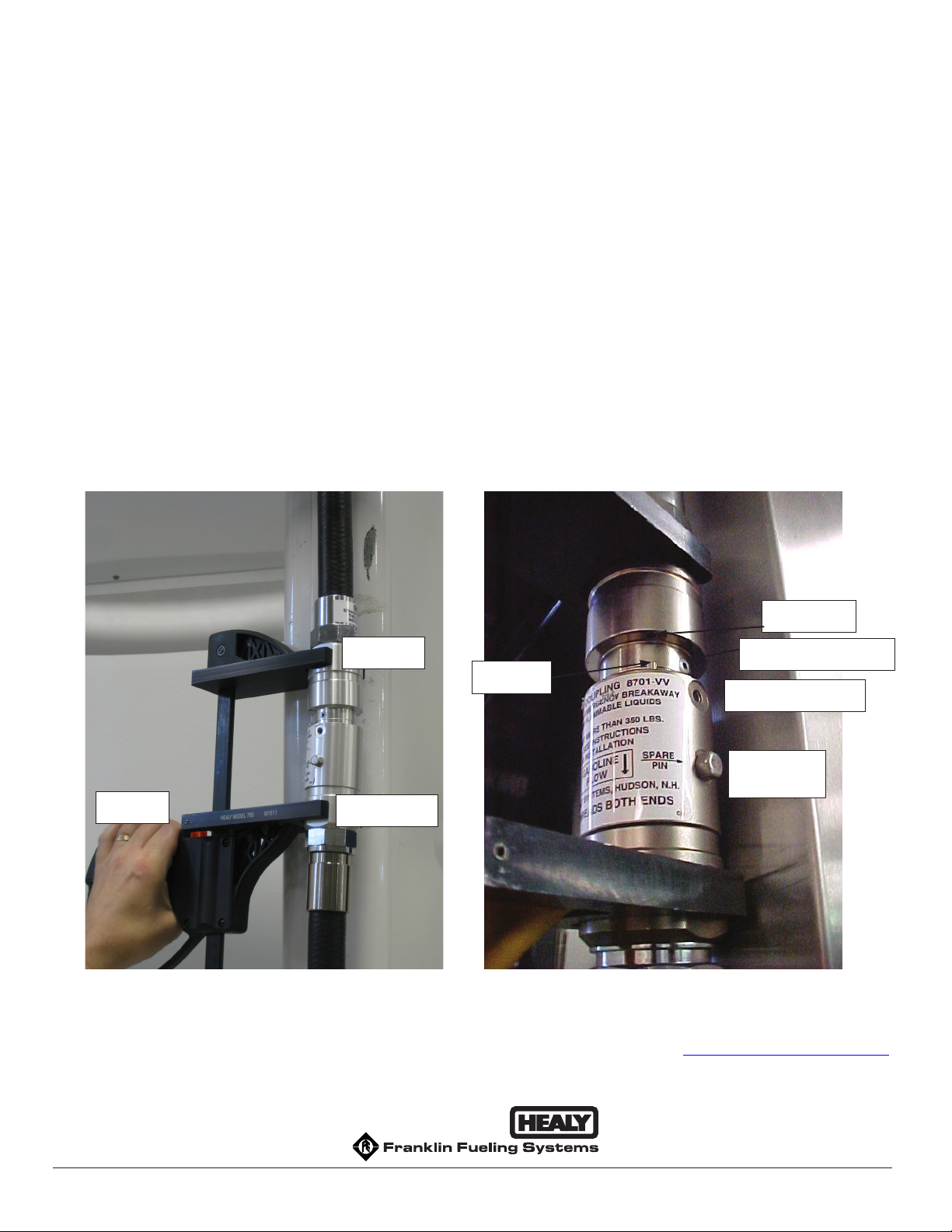
2. Check the shear pin bushing hole (see Figure 2) located in the top half of the breakaway
for any part of the pin left behind at separation. A gentle tap on the opposite side of the
breakaway should eject the pin.
3. After completing inspection, lightly lubricate the main o-ring on the top half of the breakaway.
Any weight motor oil is acceptable.
4. Slide the top clamp of the Breakaway Reconnection Clamp onto the two at surfaces on the
top half of the breakaway (See Figure 1) installed on the dispenser (attached to whip hose).
5. Slide the separated bottom half of the breakaway (with hose and nozzle attached) onto the
bottom clamp of the Breakaway Reconnection Clamp and begin squeezing the grip to slowly
bring the two halves together. Check the main o-ring for position as the top and bottom of the
breakaway come together.
6. Align the dowel pin in the bottom half of the breakaway with the dowel pin guide located in the
DRIVE-OFF BREAKAWAY RECONNECTION PROCEDURE
Use this procedure to either reconnect or disconnect (reverse order) the Healy 8701VV Breakaway as
part of Section 1.4 Procedure for Reconnecting Breakaway and Testing Fueling Point after Drive-Off
in the Assist Systems Scheduled Maintenance.
NOTE: Breakaway Reconnections must be logged in the GDF Maintenance Log.
Reconnection Procedure Option
I. HEALY BREAKAWAY RECONNECTION CLAMP .......................................................................... 1
II. EASYGRIP RECONNECTION TOOL ............................................................................................. 3
6-3
CARB Approved IOM 6 - Healy Breakaway Model 8701VV - Executive Orders VR-201 and VR-202
top half of the breakaway. When dowel pin and guide are aligned, continue squeezing tool grip
until the breakaway halves join together.
CAUTION: Reconnection can cause a small amount of gasoline to leak out of the
breakaway. A towel wrapped loosely around the breakaway can help to
minimize fuel spills.
7. Remove the shear pin (#787) located in the spare shear pin location of the breakaway and
install in place of the original.
8. Torque the shear pin to 20 inch-pounds (~ 1.5 ft-lbs). DO NOT OVER-TIGHTEN.
9. If available, install a shear pin (#787) in the spare shear pin location.
10. Remove the Breakaway Reconnection Clamp.
11. Proceed with the tests outlined in Section 1.4 of the Healy Systems Scheduled Maintenance.
Figure 1 Figure 2
Top Clamp
Bottom Clamp
Tool Grip
Dowel Pin
Dowel Guide
Shear Pin Bushing Hole
Shear Pin Installation
Spare Shear
Pin
Franklin Fueling Systems Website: http://www.franklinfueling.com
3760 Marsh Road Email: [email protected]
Madison, Wisconsin 53718 USA Telephone: 800-225-9787
ARB Approved Installation, Operation and Maintenance Manual Fax: 608-838-6433

6-4
CARB Approved IOM 6 - Healy Breakaway Model 8701VV - Executive Orders VR-201 and VR-202
II. EASYGRIP BREAKAWAY RECONNECTION CLAMP
TOOLS NEEDED:
• EasyGrip Reconnection Clamp
• 8 mm Hex Head Socket
• Torque wrench
• Safety Glasses
RECONNECTION PROCEDURE
NOTE: Additional information on the EasyGrip operation can be found by viewing a video clip on
their website at http://www.simplegrip123.com/
1. Inspect each half of the separated breakaway for obvious damage to the outer-shell, plastic
inserts or o-rings; including cracks, chips or tears that may effect reconnecting the two halves.
2. Check the shear pin bushing hole, (See Figure 1) located in the top half of the breakaway for
any part of the pin left behind at separation. A gentle tap on the opposite side of the breakaway
should eject the pin.
Figure 1

6-5
CARB Approved IOM 6 - Healy Breakaway Model 8701VV - Executive Orders VR-201 and VR-202
3. After completing inspection, lightly lubricate the main o-ring on the top half of the breakaway
(See Figure 1). Any weight motor oil is acceptable.
4. With the EasyGrip in its full open position, place the top portion of the breakaway into the top
side of the EasyGrip and the bottom portion of the breakway into the bottom side (See Figure 2).
Figure 2
5. Pull the two handles of the Easy Grip down at the same rate to slowly bring the two halves
together. Check the main o-ring for position as the top and bottom of the breakaway come
together. See Figure 3.
Figure 3

6-6
CARB Approved IOM 6 - Healy Breakaway Model 8701VV - Executive Orders VR-201 and VR-202
6. Align the dowel pin in the bottom half of the breakaway with the dowel pin guide located in the
top half of the breakaway. When the dowel pin and guide are aligned, continue squeezing tool
grips until the breakaway halves come together. See Figure 4
Figure 4
CAUTION: Reconnection can cause a small amount of gasoline to leak out of the breakaway.
A towel placed in front of the reconnection zone of the breakaway can help to
minimize fuel spills.
7. Remove the shear pin (#787) located in the spare shear pin location of the breakaway and install
in place of the original. See Figure 5
Figure 5

6-7
CARB Approved IOM 6 - Healy Breakaway Model 8701VV - Executive Orders VR-201 and VR-202
8. Torque the shear pin to 20 inch-pounds (~ 1.5 ft-lbs).
DO NOT OVER-TIGHTEN
9. If available, install a shear pin (#787) in the spare shear pin location.
10. Remove the Easygrip.
11. Proceed with the tests outlined in Section 1.4 of the Healy Systems Scheduled Maintenance.

6-1
CARB Approved IOM 6 - Healy Breakaway Model 807 Swivel - Executive Orders VR-201 and VR-202
Healy Model 807 Swivel Breakaway
hose. Tighten to 35 to 70 foot pounds. Be sure the valve and spring
(items 6 & 11) are in place before final tightening.
35 to 70 foot pounds. Be sure the vapor tube fitting slides easily into
the nozzle before final tightening.

6-2
CARB Approved IOM 6 - Healy Breakaway Model 807 Swivel - Executive Orders VR-201 and VR-202
DRIVE-OFF BREAKAWAY RECONNECTION PROCEDURE
Use this procedure to either reconnect or disconnect (reverse order) the Healy 807 Swivel Breakaway
as part of Section 1.4 Procedure for Reconnecting Breakaway and Testing Fueling Point after Drive-
Off in the Healy Systems Scheduled Maintenance.
TOOLS NEEDED:
•Healy Breakaway Reconnection Clamp, Part No. 795
•8mm Hex Head Socket
•Torque wrench
•Safety glasses
1. Inspect each half of the separated breakaway for obvious damage to the outer-shell, plastic
insert or o-rings; including cracks, chips or tears that may effect reconnecting the two halves.
2. Check the shear pin bushing hole (see Figure 3) located in the half of the breakaway attached
to the hose for any part of the pin left behind at separation. A gentle tap on the opposite side
of the breakaway should eject the pin.
3. After completing inspection, lightly lubricate the main o-ring on the half of the breakaway that’s
attached to the hose and the two small o-rings inside the half of the breakaway attached to the
nozzle. Any weight motor oil is acceptable.
4. Remove the black handle cover from the nozzle (See Figure 1).
5. Slide the top clamp of the Breakaway Reconnection Clamp above the two at surfaces on the
nozzle (See Figure 2).
6. Slide the half of the breakaway that’s attached to the hose onto the bottom clamp of the
Breakaway Reconnection Clamp and begin squeezing the grip to slowly bring the two halves
together. Check the main o-ring for position as the top and bottom of the breakaway join
together (See Figure 2).
7. Align the dowel pin in the top half of the breakaway with the dowel pin guide located in the
bottom half of the breakaway (See Figure 3). When dowel pin and guide are aligned, continue
squeezing tool grip until the breakaway halves come together (See Figure 4).
Caution: Reconnection can cause a small amount of gasoline to leak out of the
breakaway. A towel wrapped loosely around the breakaway can help to
minimize fuel spills.
6-3
CARB Approved IOM 6 - Healy Breakaway Model 807 Swivel - Executive Orders VR-201 and VR-202
7. Remove the shear pin (#787-1) located in the spare shear pin location of the breakaway and
install in place of the original.
8. Torque the shear pin to 20 inch-pounds (~ 1.5 ft-lbs). DO NOT OVER-TIGHTEN.
9. If available, install a shear pin (#787-1) in the spare shear pin location.
10. Remove the Breakaway Reconnection Clamp.
11. Proceed with the tests outlined in Section 1.4 of the Healy Systems Scheduled Maintenance.
Figure 1 Figure 2
Bottom Clamp
Tool Grip
Top Clamp
Figure 3 Figure 4
Dowel Pin
Dowel Guide
Shear Pin Bushing Hole
Shear Pin Installation
Spare Shear
Pin
Tabla de contenidos
Otros manuales de Unidad de control de Franklin Fueling Systems


Manuales populares de Unidad de control de otras marcas

Festo
Festo Compact Performance CP-FB6-E Manual de lista de piezas

Elo TouchSystems
Elo TouchSystems DMS-SA19P-EXTME Manual de usuario

JS Automation
JS Automation MPC3034A Manual de usuario

JAUDT
JAUDT SW GII 6406 Series Guía rápida

Spektrum
Spektrum Air Module System Manual de usuario

BOC Edwards
BOC Edwards Q Series Manual de usuario


