Fort Vale 0R3/ 006 Series Manual de usuario
Maintenance Manual
Part Number: 0R3/XXXX006X
2.7"NB Super Maxi
Rail Relief Valve
MM050 REV03-12.12.19
®
Uncontrolledcopywhendownloadedorprinted.PleaserefertoFortValeforupdates.

Uncontrolledcopywhendownloadedorprinted.PleaserefertoFortValeforupdates.

®
MM050_CONTENTS REV02-12.12.19
© Fort Vale Engineering Ltd. 2019
www.fortvale.com
CONTENTS
Maintenance Manual
2.7"NB Super Maxi Rail Relief Valve
Introduction 3
Maintenance Safety Precautions 4
Chapter 1 Disassemble the valve 5
Chapter 2 Assemble the valve 11
Chapter 3 Test & adjust the set pressure 17
Chapter 4 Install the anti-tamper screw 23
Appendix 27
A Tools & Equipment 28
B Bolt Torque Guide & Step Loading Procedure 29
C Client Responsibilities 31
D Data sheet: USREL147 & USREL148
2.7”NB Super Maxi pressure only rail car relief valve
Part number: 0R3/XXXX006X
33
E Data sheet: USREL185
Flanged high-pressure Super Maxi relief valve
Part number breakdown
35
MM050_REV031
Uncontrolledcopywhendownloadedorprinted.PleaserefertoFortValeforupdates.

MM050_REV03©FortValeEngineeringLtd.2019 2
Uncontrolledcopywhendownloadedorprinted.PleaserefertoFortValeforupdates.

MM050_INTRO REV00-12.12.19
© Fort Vale Engineering Ltd. 2019
www.fortvale.com
Maintenance Manual - Introduction
2.7"NB Super Maxi Rail Relief Valve
To prevent damage to the valve:
·use the recommended tools to do the maintenance and to test the valve.
IMPORTANT
This maintenance manual contains instructions to do the maintenance and testing on the 2.7" Super Maxi rail relief valve,
part number series 0R3/XXXX006X.
·use the recommended tools.
WARNING :A relief valve is a spring-loaded device which can cause serious injury to personnel. Obey
all the maintenance and safety precautions.
·be careful during maintenance.
·use the applicable PPE.
Read all the information and instructions before you start the procedure. Keep this manual.
Overview
Maintenance Precautions
To prevent injury to personnel:
·obey all warnings.
The valve illustrated in this manual is part number 0R3/X165006R with a set pressure of 165 PSIG and a raised face
flange.
·injury to personnel.
·valve malfunction.
WARNING: If you install a replacement part that is not a genuine Fort Vale part, there is a risk of:
Identify your relief valve - the part number series will be marked on the valve cap. Please contact Fort Vale to order new
seal kits and replacement parts. Install only genuine spare parts.
·permanent damage to the valve or tank.
Replacement Parts
You will need general workshop equipment and hand tools and some special tools to do relief valve maintenance. Please
refer to Appendix A: Tools & Equipment.
·obey the recommended bolting sequence and Step Loading Procedure when you remove and install the valve
(see : Bolt Torque Guide & Step Loading Procedure).Appendix B
·use genuine Fort Vale spare parts.
·read Client Responsibilities ( ).see Appendix C
If you have a problem that you cannot solve using this manual, please contact us.
Tools & Equipment
®
MM050_REV033
Uncontrolledcopywhendownloadedorprinted.PleaserefertoFortValeforupdates.

®
OPIN41 REV01-31.10.19
© Fort Vale Engineering Ltd. 2019
www.fortvale.com
Maintenance Safety Precautions
Maintenance Manual
·make sure the vessel and valves have been cleaned correctly.
·has experience and qualifications related to valve maintenance and testing.
When you have completed the maintenance, you must do an approved leak test to the valve before you install it onto the
vessel.
·knows the operation limits of the valve.
WARNING: Vessels and systems operate under pressure and can contain dangerous cargo (liquid
and gas) that can cause death or serious injury to personnel.
Before you remove a valve from the vessel/system, you must:
·make sure the vessel/system is empty (liquid and gas).
·knows the function of the valve.
Approved Person
Important Safety Notice
·make sure that the vessel/system pressure is at zero. When all the vessel/system pressure is released, use an
approved method to release all residual pressure before you loosen the fasteners.
·make sure the vessel has been certified safe for human entry.
·read the SDS (Safety Data Sheet) for the last cargo and obey the recommended precautions.
·use the applicable PPE (Personal Protection Equipment) for the cargo and operating conditions.
Precautions
·do a Hazard Identification and Risk Assessment.
You must be an “approved person” to do valve maintenance and testing. An approved person:
·knows how the valve is assembled, installed and operated.
·knows and obeys all the related in-company and regional/national regulations.
After maintenance
MM050_REV034
Uncontrolledcopywhendownloadedorprinted.PleaserefertoFortValeforupdates.

®
© Fort Vale Engineering Ltd. 2019
www.fortvale.com
CHAPTER 1
Disassemble the valve
2.7"NB Super Maxi Rail Relief Valve
This chapter contains instructions to fully disassemble the valve and the pressure plate assembly.
MM050_REV035
Uncontrolledcopywhendownloadedorprinted.PleaserefertoFortValeforupdates.
2.7”NB Super Maxi rail relief valve - Disassemble the valve
© Fort Vale Engineering Ltd 2019
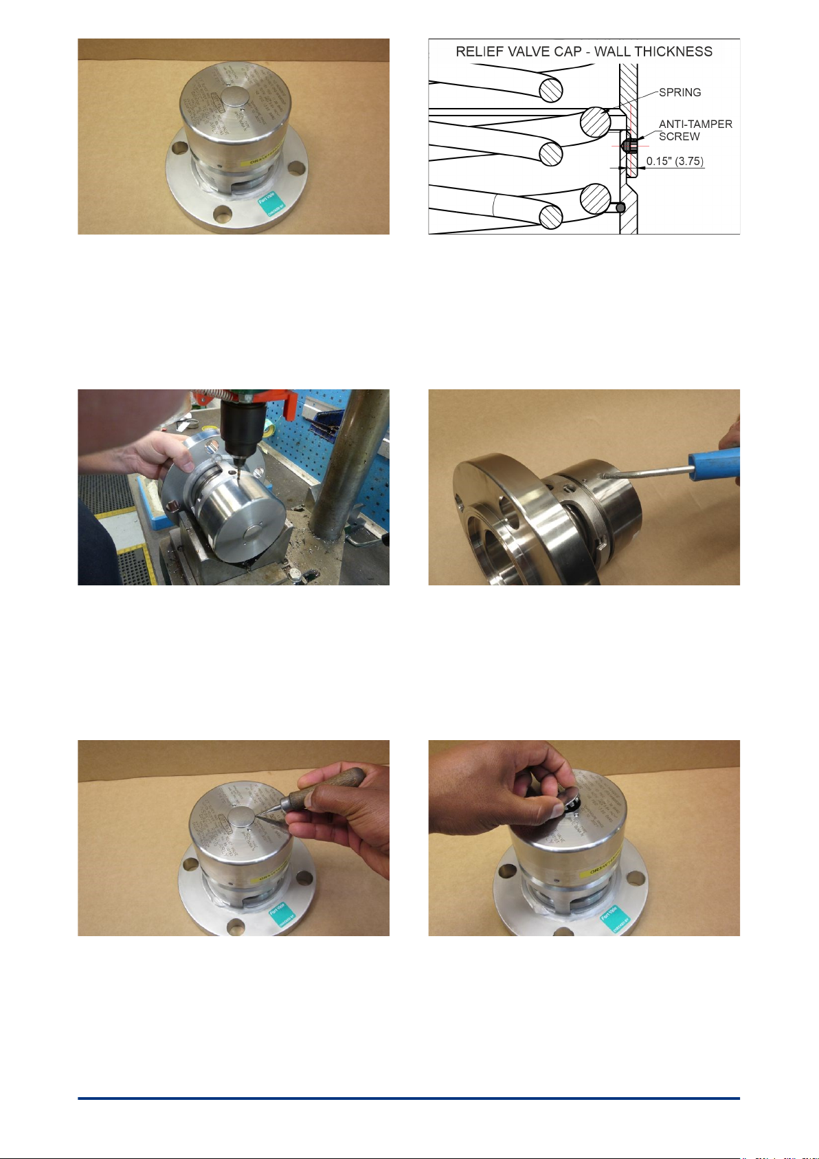
Step 1. Identify the valve. The part number will be laser
marked on the cap. If you are unsure please contact Fort
Vale. WARNING: Relief valves are spring-loaded and can
cause serious personal injury. Obey all the instructions
and wear eye protection during this procedure.
Step 2. The cap is locked to the valve body with an anti-
tamper screw filled with lead shot. Note the wall thickness
of the relief valve cap. CAUTION: It is important not to drill
fully through the cap and body because if can cause
damage to the spring.
Step 3. Put the valve on a V block on a pedestal drill. Use
a No 22 (4mm) drill and drill to a depth of 0.2" (5mm) to
remove the lead shot and screw. This will unlock the cap.
CAUTION: Do not drill to a depth of more than 0.2" (5mm)
to prevent damage to the spring.
Step 4. Clean the hole using compressed air.
Step 5. Use a sharp-edged tool to detach the stainless
steel plug.
Step 6. Remove the stainless steel plug. Keep the plug.
MM050_REV036
Uncontrolledcopywhendownloadedorprinted.PleaserefertoFortValeforupdates.
2.7”NB Super Maxi rail relief valve - Disassemble the valve
© Fort Vale Engineering Ltd 2019
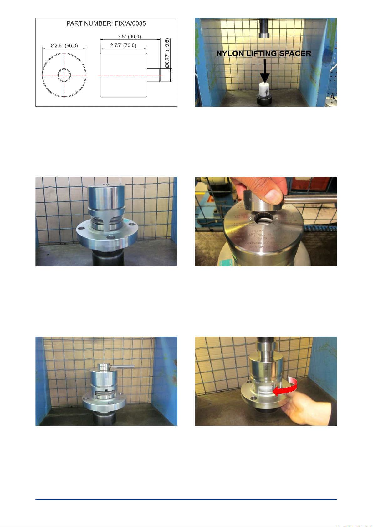
Step 7. Select the nylon lifting spacer, part number
FIX/A/0035.
Step 8. Install the nylon lifting spacer onto a bench press
with a minimum 1 tonne load.
Step 9. Install the valve onto the spacer. Make sure that
the valve is central on the spacer.
Step 10. Select the cap tightening tool, part number
FIX/A/0034. Engage the two pins on the cap tightening
tool into the two blind holes of the top cap.
Step 11. Make sure that the cap tightening tool is
installed correctly on the cap.
Step 12. Apply pressure onto the top cap tightening tool
until the spring is compressed enough so that the valve
body is free to move. Then turn the valve body clockwise
until it is disassembled from the top cap. WARNING: Make
sure that you lock the press before you start to unscrew
the valve.
MM050_REV037
Uncontrolledcopywhendownloadedorprinted.PleaserefertoFortValeforupdates.
2.7”NB Super Maxi rail relief valve - Disassemble the valve
© Fort Vale Engineering Ltd 2019
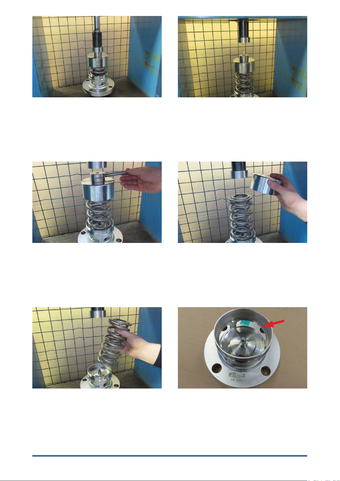
Step 13. When the valve and the cap are disassembled,
unlock the press and gradually retract the press to release
the spring load. WARNING: Be careful when you retract
the press. Make sure that the spring is fully decompressed
before you remove the ram.
Step 14. When the spring is fully decompressed, retract
the ram fully.
Step 15. Remove the cap tightening tool. Step 16. Remove the top cap. Examine the top cap for
signs of damage or wear. If there is damage, contact Fort
Vale.
Step 17. Remove the springs. Examine the springs for
signs of corrosion or damage. If there is damage, contact
Fort Vale.
Step 18. Remove the valve body and pressure plate from
the press and put it onto a work bench.
NOTE: Valves manufactured after March 2017 have a
retaining ring clip installed in a groove in the valve body.
MM050_REV038
Uncontrolledcopywhendownloadedorprinted.PleaserefertoFortValeforupdates.
Tabla de contenidos
Otros manuales de Unidad de control de Fort Vale

Manuales populares de Unidad de control de otras marcas

Festo
Festo Compact Performance CP-FB6-E Manual de lista de piezas

Elo TouchSystems
Elo TouchSystems DMS-SA19P-EXTME Manual de usuario

JS Automation
JS Automation MPC3034A Manual de usuario

JAUDT
JAUDT SW GII 6406 Series Guía rápida

Spektrum
Spektrum Air Module System Manual de usuario

BOC Edwards
BOC Edwards Q Series Manual de usuario


