FONESTAR MPX-4088 Manual de usuario

MPX-4088, MPX-400MIC, MPX-410ES,
MPX-420V, MPX-430VS AND MPX-440X
AUDIO MATRIX
INSTRUCTION MANUAL

EN
- 2-
We take this opportunity to thank you for buying this product.
We recommend you read the instruction manual before switching on the machine and follow the instructions
that are given. Keep the manual for future reference.
SECURITY AND THE ENVIRONMENT
ELECTRICAL SECURITY
Check that the current in the mains connection where the machine is to be installed corresponds to the
power supply of the machine.
To avoid damaging the equipment, electrical shocks, fire or physical injury when you connect or disconnect
the equipment from the power supply, pull the plug firmly out of the mains socket holding the plug, never the
cable.
Always do this with dry hands.
Keep the power supply cable far from sources of heat. Do not put heavy objects on top of it or change it.
Clean dust and dirt off the power supply cable regularly.
Do not open the machine; you could get an electric shock.
CAUTION
While installing the machine, make sure it is switched off and unplugged.
Do not open the machine. Touching the internal parts is dangerous and you could receive an electric shock.
The machine must not be splashed or dripped on. Never place recipients with liquid inside on the machine.
Do not place anything inside the machine.
LOCATION
Place the equipment on a horizontal surface with enough space around it to allow ventilation.
Avoid direct sunlight, heat sources and excessive dust.
Do not place the machine near magnetic fields or static electricity.
Do not use surfaces which vibrate or receive impact.
Do not pile machines on top of one another.
VENTILATION
Never block or cover the ventilation slits on the machine.
Do not expose it to direct sunlight or place it near sources of heat.
PERIODS OF INACTIVITY
When the machine is not going to be used for a long period of time, disconnect it from the mains.
If you are using an adapter, take into account that it will continue using electricity even if the machine is
switched off. If it is not going to be used for a long period of time, disconnect it from the mains.
THE ENVIRONMENT
To save energy, switch the machine off when you are not going to use it for a long time. The machine could
contain substances that are harmful to the environment or human health. To minimize the effect of these
substances the machine must be correctly managed and recycled when you decide to dispose of it.
When you dispose of it remember: it cannot be thrown into a conventional rubbish bin.
If it contains or uses batteries, these must be disposed of separately.
The machine (without batteries) must be disposed of correctly. Put it in a container specially intended for the
collection of electronic and electrical appliances, at the dump or hand it over to the dealer when you purchase
similar equipment, so that the dealer can dispose of it correctly (at no added cost).

SIGNIFICANCE OF THE SYMBOLS ON THE MACHINE*
The symbol formed by the expression “Class 1 laser product” written in a rectangle
indicates that visible or invisible laser radiation could be produced. Avoid direct exposure
to the laser.
The symbol formed by a ray of lightening inside a triangle shows that the machine has
connection terminals or a circuit with areas with a current which could cause an electric
shock, even in normal working conditions.
The symbol formed by an exclamation mark in a triangle shows that the instruction manual
must be referred to for information on how the machine works and its use.
The symbol formed by one square inside another square shows that the machine has
double electrical insulation.
The European Community symbol shows that the machine complies with the current
European Union legislation, as well as its transposition to local legislation.
The symbol of a rubbish bin crossed out and over a horizontal line shows that when the
product is disposed of it must be done properly, placing it in a special selective electronic
and electrical equipment container or through a dealer when purchasing a similar product,
at no additional cost. It also shows that the machine was put on the market after 13th
August 2005 (European Community Directive 2002/96/CE of Electrical and Electronic
recycling, and its Spanish equivalent R.D.208/2005).
In accordance with what is set out in the aforementioned decree, FONESTAR is registered
in the RAEE (Registro de Aparatos Eléctricos y Electrónicos) in a special section REI
(Registro de establecimientos Industriales), with the entry number 001851.
*It is possible that some of these symbols do not appear on the machine.
EXEM TION OF LIABILITY
The characteristics of the equipment and the content of the manual can change without forewarning.
FONESTAR, S.A. does not assume responsibilities regarding the inappropriate use of the equipment or the
information supplied in this instruction manual, and specifically disclaims any implied liability for marketability
or fitness for any other use.
All rights reserved by FONESTAR, S.A.
- 3-
EN

DESCRI TION
The model M X-4088 is an audio matrix with 8 analogue input channels to 8 output zones and 4 configurable
digital channels.
It has 8 analogue input channels to 8 output zones and 4 configurable digital channels. Musical source
selection, volume and equalization control for each zone through PC software or via the optional zone controls
mod. M X-420V or M X-430VS. DSP function in inputs/outputs, priority control and feedback suppressor.
Priority paging using optional microphone with zone selector mod. M X-400MIC.
A highly versatile system which is suitable for installations of any size, allowing music to be selected in each
zone. Perfect for commercial installations, conference rooms, etc.
CONTROLS AND FUNCTIONS
FRONT ANEL
1.- LCD DIS LAY: information display:
a.- Device name.
b.- Selected preset.
c.- Software version.
d.- Connection status between PC and device. If the connection is
correct, both icons will flash alternatively.
e.- DSP indicator. Should a problem occur “DS !” will be displayed.
f.- Device ID number. It is obtained automatically when switched on.
2.- ANALOG IN UT: LED analogue input indicators:
-SIGNAL: indicates signal presence in the corresponding input channel.
-CLI : indicates signal saturation in the corresponding input channel.
3.- RD IN UT: digital input LED indicators:
-SIGNAL: indicates signal presence in the input channel.
-CLI : indicates signal saturation in the corresponding input channel.
4.- ANALOG OUT UT: LED analogue output indicators:
-SIGNAL: indicates signal presence in the input channel.
-CLI : indicates signal saturation in the corresponding output channel.
5.- RD OUT UT: digital output LED indicators:
-SIGNAL: indicates signal presence in the corresponding output channel.
-CLI : indicates signal saturation in the corresponding output channel.
6.- STATUS:
-FAULT: indicates a fault with the DSP.
-COM: provides information about the communication between the PC and the device. A light flashes
when there is data transmission between them. It remains switched off if there are communication
problems.
-OWER: matrix LED power indicator.
- 4-
EN

REAR ANEL
1.- 100-240 V AC power supply.
2.- Ethernet port. RJ-45 connector.
3.- RC-NET IN/LINK: input/output for interconnection of several M X-4088 devices. Connect the LINK
output to the IN input of the next matrix and so on with the rest of the matrices up to a maximum of 16
matrices, 192 inputs and 192 zones. The matrices are configured using the PC software. RJ-45
connector.
4.- RD 9/10 - 11/12: ports corresponding to the digital input and output channels, 9/10 and 11/12. They
allow the connection of models M X-400MIC, M X-410ES, M X-420V, M X-430VS for sending and
receiving of control and digital audio signals. RJ-45 connector.
5.- RELAY: contact closures that can be controlled individually using PC software. They can be used as
switches for other electric devices. Euroblock terminals.
6.- IN UT/OUT UT (1-8): balanced analogue audio input/output euroblock terminals. 48 V phantom power
supply available via PC software.
7.- FUSE: AC power supply protective fuse.
8.- LAN/RC-NET: allows the type of communication to be selected in the LAN port (2) between, TCP/IP in
LAN position or RS-485 in RC-NET position.
9.- RS-232: euroblock terminals to control via the series port.
ST CABLE FOR RD ORTS
The RD ports transmit and receive AES3 Plus control signals. Below, the PIN-OUT is shown for an RJ-45
connector and STP cable.
Note: do not connect an RD port to a router, the router could be damaged.
- 5-
EN

EN
- 6-
CONNECTION
CONNECTION OF BALANCED AUDIO IN UTS 1 TO 8 AND REMOTE ZONES
Connect the analogue audio sources/microphones to the inputs 1 to 8 on the rear panel of the mod.
MX-4088. The order in which the inputs are connected will allow their selection for each of the zones via
software or zone controls.
If the zones are equipped with the remote audio input/output control mod. M X-410ES, it is possible to
connect the source directly to the microphone or line input, corresponding to the 9/10 or 11/12 lines
according to which RD port on the M X-4088 matrix it has been connected to. Each matrix supports a
maximum of two M X-410ES connected and operating at the same time.
CONNECTION OF MICRO HONES WITH ZONE SELECTORS
Connect the microphones with zone selector mod. M X-400MIC, up to a maximum of 2 units, to the RD 9/10
or 11/12 inputs on the rear panel of the mod. M X-4088, using shielded Cat 5e cable with RJ-45 connector.
Note: it supports the connection of two M X-400MIC microphones maximum per matrix, for non-
simultaneous use.
ZONE OUT UT CONNECTION
Each matrix mod. M X-4088 has 8 independent zones with balanced line level output for the connection of
a power amplifier or amplifier per zone. Connect the output of each of the zones to a line level input of a
corresponding power amplifier. Control the output volume with the PC software or using the remote control
mod. M X-420V or M X-430VS and then regulate the level of the power amplifier in order to achieve a
suitable level of volume in the loudspeakers in the zone. It is possible to extend the output zones to 12 with
the connection of 2 M X-410ES audio input/output controls or 2 M X-430VS zone controls with audio
output.
CONNECTION OF ZONE CONTROLS
Each of the output zones can be controlled remotely using the controls mod. M X-420V or mod.
M X-430VS. These controls allow the selection of any of the selectable inputs 1 to 12 of the matrix mod.
M X-4088, as well as the regulation of the volume of each remote zone. The M X-430VS control
incorporates two audio outputs corresponding to the channels 9/10 or 11/12 according to the RD port on the
M X-4088 matrix to which it has been connected.
Connect the M X-420V or M X-430VS control with Cat 5e or higher cable, RJ-45 connector to the RD ports
9/10 or 11/12 on the matrix.
Note: up to 8 M X-420V controls can be connected in series as a maximum, for a maximum distance of 150
meters with shielded Cat 5e or higher network cable.
GENERAL CONNECTION RECOMMENDATIONS
Make the connections with the matrix and all the components of the audio system switched off and
disconnected from the power supply. Always begin with the volume controls at their minimum. Move the
controls slowly.
Firstly, connect the audio sources to the inputs. A bad connection can cause noise and interference. Use
suitable cables that are not excessively long to make the connections: shielded cables, preferably low
capacity.
Connect remote controls mod. M X-420V or M X-430VS in the required zones and the microphone with
zone selector mod. M X-400MIC, the remote audio input/output control mod. M X-410ES or the extender
M X-440X to the matrix RD ports using Cat 5e or higher cable.
Connect a power amplifier to the OUTPUT of each zone you are going to use. 100 V line or low impedance
4-8 Ω amplifiers can be used depending on the type of loudspeakers that are going to be connected. Once
the connections have been made, connect the devices to the mains supply and switch them on. After use,
do not forget to switch them off and disconnect the device from the mains supply.

CONNECTION EXAM LES
With the audio matrix mod. M X-4088 it is possible to configure systems of 12 to 192 zones. The basic
system allows connection of up to a maximum of 12 inputs and 12 outputs per matrix. With the optional mod.
M X-450D (DANTETM module), the interconnection of up to 16 M X-4088 matrices is possible for a total of 192
inputs and 192 outputs, making it compatible with other DANTETM systems. The configuration and allocation of
inputs and outputs can be performed using the PC software or the M X-420V or M X-430VS zone controls.
The matrix has up to 8 analogue audio inputs, 8 zone outputs and two RD ports with 4 audio input/output
channels for the connection of models M X-400MIC, M X-410ES, M X-420VS or extending the RD ports
with the mod. M X-440X.
Below, the different connection configurations are shown:
CONFIGURATION 1
- RD port 9/10: M X-400MIC microphone with zone selector for priority paging.
- RD port 11/12: M X-420V zone controls, without exceeding a maximum of 8 devices in series and a
distance of 150 meters for a shielded Cat 5e or higher cable.
CONFIGURATION 2
EN
- 7-

EN
- 8-
With the port extender mod. M X-440X connected as shown in the previous diagram, 4 audio input/output
channels are available corresponding to the audio port of mod. M X-440X and the RD 9/10 matrix port and
3 control ports on the mod. M X-440X for the connection of M X-420V zone controls. Up to a maximum of
8 units of the model M X-420V can be connected in series by port and a maximum cable distance of 150
meters for a shielded Cat 5e or higher network cable.
CONFIGURATION 3
With the two M X-4088 matrices connected as shown in the diagram above, up to 16 analogue audio inputs
can be connected to 16 selectable zones, 4 M X-400MIC microphones with zone selectors or 4 M X-410ES
audio input/output controls, plus the M X-420V or M X- 420VS zone controls. With the optional M X-450D
model, the interconnection of up to 16 M X-4088 matrices is possible for a total of 192 inputs and 192 outputs,
making it compatible systems with other DANTETM systems.
EN
- 9-
CONFIGURATION AND CONTROL SOFTWARE
The matrix M X-4088 is configured using PC software. In order to download the software, access our
website fonestarpro.com and find the product M X-4088. Then, open the “Software” tab to download the
file in your computer and install the software. This software is compatible with Windows 7 or higher. The
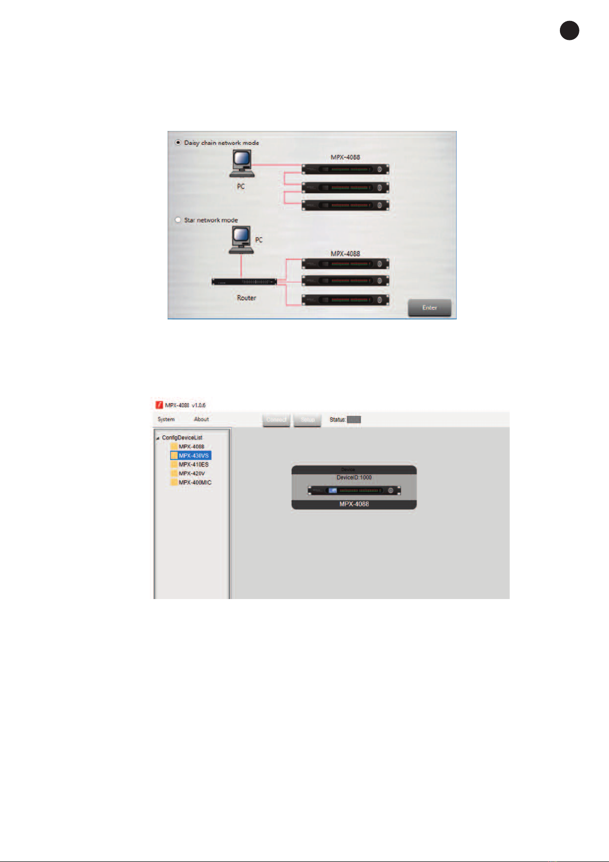
software has two connection modes for the configuration of the matrix.
1.- Daisy chain network mode: allows configuration of the matrix M X-4088, as well as the optional models
M X-400MIC, M X-410ES, M X-420V and M X-430VS. In this edition mode, the PC and the matrix
M X-4088 must be connected directly by RJ-45 cable and the LAN/RC-Net selector located on the rear
panel of the matrix, must be in the LAN position.
It is necessary to establish the IP address of the matrix. To do so, click on the SETUP button and, then,
on SCAN to begin the automatic search for the IP and MAC address of the M X-4088 matrix.

Select the line with the IP and MAC address of the M X-4088 matrix and click on APPLY. Then, click on
CONNECT and the STATUS indicator should turn green. Add the devices located in the sidebar by
dragging them into the grey area.
Double click on the required device module to access the edition mode.
Note: when several matrices are connected in cascade, the LAN/RC-Net connector must be in the LAN
position on the matrix that is directly connected to the PC, and in the RC-Net position on the rest of the
matrices that are connected to each other. To access the configuration of each device, it is necessary to
establish the device’s ID manually by right-clicking on the device to be configured and accessing “Change
Device ID”.
2.- Star network mode: allows the configuration and individual control of several M X-4088 matrices
connected to the same router. In this edition mode, the PC and the M X-4088 matrix must be connected
to the router with RJ-45 cable and the LAN/RC-Net selector located on the rear panel of the matrix must
be in the LAN position.
In this edition mode, the system automatically detects the M X-4088 matrices connected to the network
for their configuration and control.
- 10 -
EN
Otros manuales para MPX-4088
1
Este manual sirve para los siguientes modelos
5
Tabla de contenidos
Otros manuales de Conmutador de matriz de FONESTAR

FONESTAR
FONESTAR FO-22M42 Manual de usuario

FONESTAR
FONESTAR FO-22M88 Manual de usuario

FONESTAR
FONESTAR FO-14M42 Manual de usuario

FONESTAR
FONESTAR FO-22M44 Manual de usuario

FONESTAR
FONESTAR FO-20M44XT Manual de usuario

FONESTAR
FONESTAR FO-14M44E Manual de usuario

FONESTAR
FONESTAR FO-455M Manual de usuario


