FLYGT CAS Manual

Installation and service
CAS
894635/01
Installation och skötsel
Montage unde Service
Installation et entretien
Instalación y servicio
Installazione e manutenzione

English, page 3
Svenska, sid 13
Deutsch, Seite 23
Français, page 33
Español, página 43
Italiano, pagina 53

3
GUARANTEE
CONTENTS
Page Page
CONTENTS
General__________________________________ 4
Functions________________________________ 4
Eletrical connection ________________________ 6
ITT Flygt undertakes to remedy faults in products sold
by ITT Flygt provided:
— that the fault is due to defects in design, materials
or workmanship
— that the fault is reported to ITT Flygt or ITT Flygt’s
representative during the guarantee period
— that the product is used only under conditions
described in the care and maintenance instructions
and in applications for which it is intended
— that the monitoring equipment incorporated in the
product is correctly connected
— that all service and repair work is done by a
workshop authorized by ITT Flygt
— that genuine ITT Flygt parts are used.
Hence, the guarantee does not cover faults caused
by deficient maintenance, improper installation,
incorrectly executed repair work or normal wear and
tear.
ITT Flygt assumes no liability for either bodily injuries,
material damages or economic losses beyond what is
stated above.
ITT Flygt guarantees that a spare parts stock will be
kept for 15 years after the manufacture of this product
has been discontinued.
The manufacturer reserves the right to alter perfor-
mance, specification or design without notice.
Tehnical data_____________________________ 7
Fault tracing (trouble shooting) _____________ 8
Scheme of functions ______________________ 12
English

4
These instructions do not apply to units delivered
with article number 83 58 41, which are programmed
for other functions. The fault tracing scheme applies
to the standard version 83 58 40 only.
The figures in the text refer to the numbers on the
front cover (1 – 32) and also to the picture below
(51 – 61).
GENERAL
Channel A, liquid level
This channel is used, for example, for monitoring of
possible liquid leakage into the stator casing. A sensor
is incorporated in the lower part of the stator casing.
The sensor changes resistance from about
1.5 kΩto about 330 Ωif liquid enters.
Another sensor that can be connected to this channel
is the water in oil sensor, called CLS (capacitive
leakage sensor). The CLS-30 monitors the content of
water in the oil housing or the gear box and alarms at
a percentage > 35.
Input indication
The pilot lamp 51 is lit to indicate interruption or short-
circuit.
Alarm
After alarm for about 5 seconds, the alarm function A
is activated, the red pilot lamp 53 is lit, the Σ-alarm
function is activated (the pilot lamp is lit) and the
interlock (11 – 12) drops, whereby the pump/turbine is
disconnected and the pilot lamp 59 will go out.
Reset
Resetting can only be done manually, by pushing the
reset button connected to the entrance (22, 23).
Flygt’s monitoring unit, 83 58 40, is designed for use in
pumps from model 3231 and larger models equipped
with drive units 680-945. Turbines equipped with
generators 705-935 are also covered by the monitoring
system.
The monitoring unit is connected to the standardized
range of sensors incorporated in all the products
covered.
FUNCTIONS

5
Channel B, oil pressure
(or liquid level)
This channel with RUN connected to a normally open
contact is to be used to monitor the oil pressure in
machines equipped with a gear unit. On machines
without a gear unit, the channel can be used in the
same manner as channel A, provided that RUN is not
connected.
Input indication
The pilot lamp 52 is lit to indicate interruption or
shortcircuit. If the channel is not used (machines
without a gear unit) the pilot lamp will always light.
Alarm
After an alarm from the sensor for about 5 seconds,
the alarm function B is activated, the pilot lamp 54 is
lit, the Σ-alarm function is activated, the pilot lamp 57
is lit and the interlock (terminals 11 and 12) drops,
whereby the pump/turbine is disconnected and the
pilot lamp 59 will go out.
Reset
Resetting can only be done manually.
Channel C, temperature
monitoring
This channel is intended to monitor the stator’s
temperature with thermal switches or up to 3 PTC
thermistors. The thermal switches are normally closed
but they open at 140°C ± 5°C (284°F).
Alarm
When the resistance exceeds 3 kΩ, the alarm function
C is activated, the pilot lamp 55 is lit, the Σ-alarm
function is activated, the pilot 57 is lit and the interlock
(terminals 11 and 12) drops, whereby the pump/
turbine is disconnected and the pilot lamp 59 is put
out.
Reset
Resetting can only be done manually and only when
the resistance has fallen to about 900 Ω, i.e. the stator
has cooled down.
Channel D, Pt 100 sensor
This channel is used for monitoring and analog
indication of the temperature of the main (lower)
bearing. The channel can only be connected to a
temperature sensor of type Pt-100 (DIN 437 60).
The alarm value can be set by potentiometer 60
(see “Fault tracing”). The unit is delivered set to an
alarm value of 100°C (212°F).
Indicator instrument
(extra equipment)
The channel has an output for analog reading of the
bearing temperature. An indicator instrument can be
connected to terminals 31 and 32 (NOTE! Correct
polarity ±). The instrument shows the Pt-100 sensor’s
temperature. If switch 58 is depressed, the instrument
shows the set alarm value.
Alarm
When the alarm value is reached, the alarm function
is activated, the pilot lamp 56 is lit and the Σ-alarm
function is activated. The pilot lamp 57 is lit and the
interlock (terminals 11 and 12) drops, whereby the
pump/turbine is disconnected and the pilot lamp 59
will go out.
Reset
Resetting can only be done manually.
English

6
ELECTRICAL CONNECTIONS
The monitoring unit is designed to be installed in a
control panel. The unit can be mounted either on a
35 mm symmetric DIN rail, or directly on a mounting
plate.
The drawing on page 6 shows the positioning of the
drill holes for mounting on a flat surface. The electrical
connections shall be made in accordance with the
electrical diagram (see also the top of the unit).
Connect a 24 VAC power source to terminals 14 and
16. Connect a normally open spring switch for reset
after alarm between terminals 22 and 23.
Connect the starter’s interlock circuit between
terminals 11 and 12 so that the pump/turbine is shut
off when an alarm is issued.
Connect 29 and 30 with a jumper, except when a
3-lead system for compensation for the resistance of
the sensor leads is used.
Check before start that all leads are connected to the
right terminals and that the screws are tightened.
Disconnect all connections with voltages higher than
24 V before working on the unit.

7
Supply voltage 24 V AC ±10 % 50 – 60 Hz
Power consumption Max 5 VA
Dimensions mm (in) (W × H x D) 150×70×112 (5.9×2.75×4.4)
Temperature range 0°C – + 50°C (32°F–122°F). Max 80% RH
Channel A
Voltage to detector 12 V DC
Alarm I > 20 mA
Output alarm Solid state relay 24 V AC, 100 mA
Channel B
Voltage to detector 12 V DC
Alarm I > 20 mA
( I < 20 mA if RUN is activated)
Output alarm Solid state relay 24 V AC, 100 mA
Channel C
Alarm R Ω3kΩΩ
Output alarm Solid state relay 24 V AC, 100 mA
Reset Manual when R < 900 Ω
Channel D
Alarm R > Rset
Output alarm Solid state relay 24 V AC, 100 mA
Output Max. load approx. 250 Ω
0 – 20 mA range 50°C – 150°C
(122°F–302°F) (0,2 mA/°C ±2,5 %)
ΣΣ
ΣΣ
Σ-alarm
Alarm Activated by alarm from each
individual channel
Output alarm Solid state relay 24 V AC, 100 mA
Interlock
Alarm Activated by alarm and supply failures
Function Normally closed
Breaking capacity 240 V 4 A vid cos
ϕ
= 1
Drilling instruction
TECHNICAL DATA
English

8
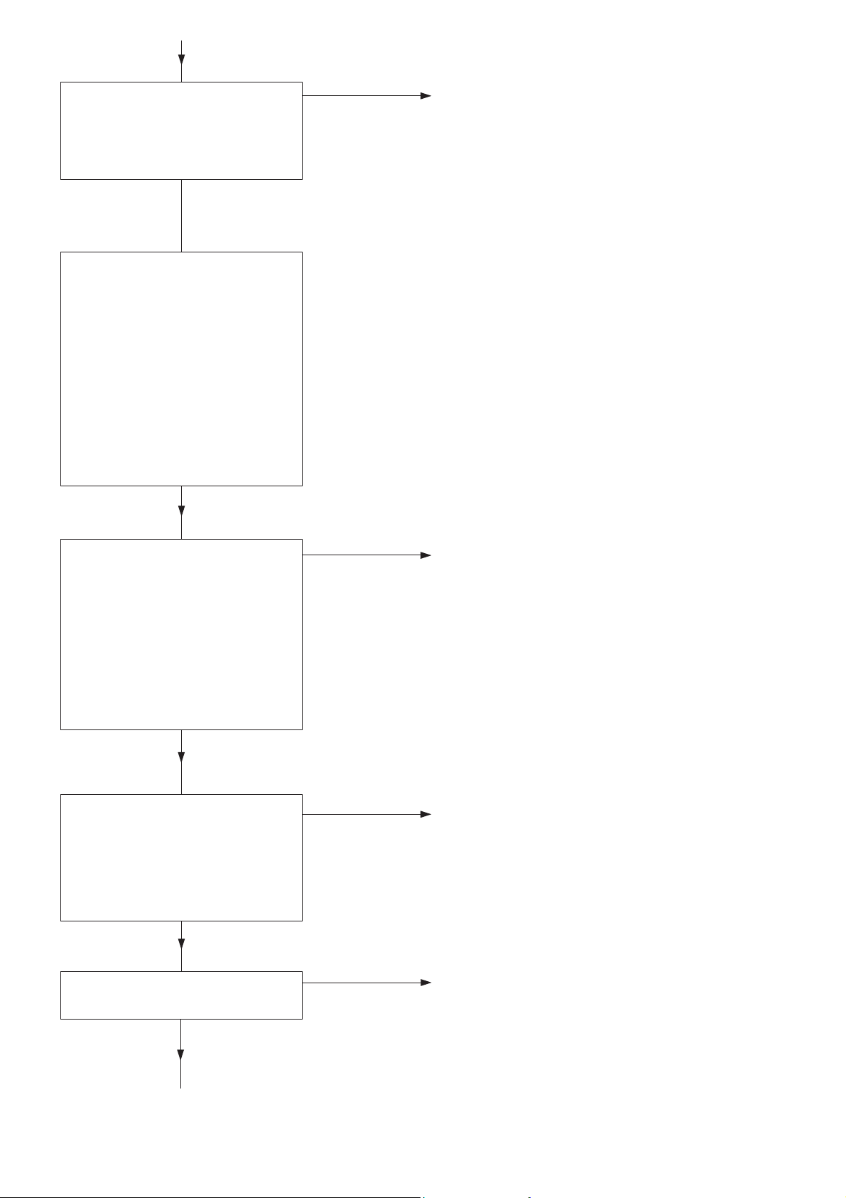
FAULT TRACING (TROUBLE SHOOTING)
With the aid of a multimeter and a couple of resistors,
it is possible to check from the outside whether the
unit is functioning properly. The multimeter shall have
an internal resistance of at least 20 kΩ/volt.
In order for the monitoring unit to function properly,
the supply voltage must lie within the specified limits,
i e 24 V AC ±10 %.
It is important to check the value of the resistors
before using them to check the D-channel. All
functions shall be tested during fault tracing. If any
function is not right, contact your ITT Flygt service
shop.
Supply voltage
No
Is pilot lamp 61 lit ? Check that supply current is
correctly connected.
Yes
No
Connect the multimeter to Investigate possible faults in the
terminals 14 and 16. power supply.
Is the voltage 21.6 – 26.4 V AC?
Yes
Channel A No
Connect the multimeter to Check the supply voltage.
terminals17 and18. Contact an ITT Flygt service shop.
(NOTE! Correct polarity ±.)
Is the voltage 10.8 – 12 V DC?
Yes
No
Disconnectthe leakage sensor. Contact an ITT Flygt service shop.
Does pilot lamp 51 light ?
Yes
No
Connect the resistor, 330 ΩContact an ITT Flygt service shop.
1/2 watt (or reference sensor)
between terminals 17 and 18.
Does the pilot lamp 51 go out ?
Yes
No
Is A-alarm activated after Contact an ITT Flygt service shop.
about 5 seconds ?
Yes

9
Channel B No
Connect the multimeter to Check the supply voltage.
terminals19 and20. Contact an ITT Flygt service shop.
(NOTE! Correct polarity ±.)
Is the voltage 10.8 – 12V DC?
Yes
No
Disconnectthe sensorand Contact an ITT Flygt service shop.
the RUN-switch. Does the
pilot lamp 52 light?
Yes
No
Connect the resistor, 330 ΩContact an ITT Flygt service shop.
1/2 watt (or reference sensor)
between terminals 19 and 20.
Does the pilot lamp 51 go out ?
Yes
No
Is B-alarm activated within Contact an ITT Flygt service shop.
5 seconds ?
Yes No
Disconnect the resistor Contact an ITT Flygt service shop.
(or reference sensor).
Reset B-alarm. Activate the
RUN-function by jumpering
24 and 25.
Is B-alarm activated after
about 30 seconds?
Yes
Channel C No
Disconnect the sensor from Contact an ITT Flygt service shop.
terminals 26 and 27.
Is C-alarm activated?
Yes
Yes
CanC-alarmbereset Contact an ITT Flygt service shop.
manually?
No
English
10
No
Connect the resistor 680 ΩContact an ITT Flygt service shop.
or 820 Ω(or a jumper),
between terminals 26 and 27.
Can C-alarm be reset
manually?
Yes
Channel D
Connect an ammeter to
terminals 31 and 32 (NOTE!
Correct polarity ±).Depress
switch 58. The instrument
shall now indicate the set
alarm level (from factory,
set to 100° C (212°F), which
corresponds to 10 mA).
For test of the channel D-alarm
function, the instrument
shall indicate 7 – 14 mA.
Adjust if necessary with
potentiometer 60.
No
Turn off the supply current. Contact an ITT Flygt service shop.
Disconnect the sensor from
terminals 28, 29 (and 30).
Connect a jumper between
29 and 30. Connect a resistor
130 Ωbetween terminals
28 and 29. Turn the supply
current back on. Does the
instrument indicate about
5.5 mA?
Yes
No
Turn off the supply current. Contact an ITT Flygt service shop.
Substitute a 150 Ω resistor
for the 130 Ω resistor. Turn the
supply current on. Does the
instrument indicate about
16 mA?
Yes
No
Is D-alarm activated and Contact an ITT Flygt service shop.
cannot be reset?
Yes
Tabla de contenidos
Idiomas:
Otros manuales de Controladores de FLYGT


