Flo CoRe+ Manual de usuario

CoRe+TM
Cable management
system and pedestal
installation guide


CoRe+TM
Cable management system and pedestal installation guide
3
Cable Management System Guide . . . . . . . . . . . . . . . . . . . . . . . . . . . . . . . . . . . . . 4
Wall mounted installation .............................................5
Cable management system installation ................................7
Single charging station installation.....................................8
Cable management system installation ................................9
Dual back-to-back charging station installation.........................10
Cable management system installation ...............................11
Dual side-to-side charging station installation ..........................12
Side-to-side charging station supports and cable management
systems Installation.................................................13
Positioning the cable clamp ..........................................15
Positioning the poster panel..........................................16
Pedestal Specications..............................................18
Maintenance and Safety .............................................19
Pedestal Dimensions ................................................20
Pedestal Installation.................................................21
Conduit Positioning .................................................22
1 or 2 devices on separate Electrical Circuits ...........................23
Multiple Pedestals, Multiple Devices on independent Electrical Circuits....24
Multiple Pedestals, Multiple Devices sharing the same Electrical Circuit ...25
Multiple Pedestals, Multiple Devices sharing the same Electrical Circuit,
but with Circuit Breaker for each Devices ..............................26
Table of contents

CoRe+TM
Cable management system and pedestal installation guide
4
Cable Management System Guide
This guide aims at describing how to install a Cable management system on a new charging station
or on a device that has already been installed.
The Cable management system is reliable, made from aluminum and convenient to use. It’s maintenance
free and keeps cables safely off the ground.
The instructions have been adapted for each type of installation. There are four types: a) wall mounted
installation; b) single charging station installation; c) dual back-to-back charging station installation;
d) dual side-to-side charging station installation. Make sure to refer to the proper section of this guide,
according to the type of installation you are about to do.
Other than instructions, you will nd in this guide the list of parts that are included in the package,
depending on the type of installation, as well a list of specic tools or material required to do the work
as the case may be.

CoRe+TM
Cable management system and pedestal installation guide
5
www
Wall mounted installation
Specic Tools or Material Required
• Wall attachment hardware material (¼ in diameter screw, washers and wall anchors as required)
BEFORE GETTING STARTED
! When unpackaging the Cable management system, make sure to remove the security screw
used to hold the counterweight during transport.
¡
Installing a new charging station and a Cable management system.
First, install the charging station. Refer to the CoRe+TM Installation Guide. Then, install the Cable
management system as indicated on the following page.
¡
Installing a Cable management system on an existing wall mounted charging station.
Install the Cable management system as indicated on the following page.
Included material Qty
Wall mounted cable management system columns and cable clamp 1
Lower wall mount bracket 1
Upper wall mount bracket 1
Spacing shims 2
Self-adhesive rubber band 6 in X 13/8 in 1
¼-20 x 2¾ screw, ¼-20 bolt and Split lock washer 1

CoRe+TM
Cable management system and pedestal installation guide
6
• Determine where the wall mount (column) will be placed. Allow 12 to
14 in between the column and the charging station.
• Determine what wall attachment hardware is required (wall anchors,
screws and washers) to securely install the mount brackets to the
wall. Use ¼ in diameter screws and anchors of the appropriate size, if
the screws cannot be secured directly in a wall stud.
Recommendations : Install the column at least 6 in from the ground
(allow enough clearance to facilitate floor cleaning). The upper wall mount
bracket should be installed at least 60 in above the lower wall mount
bracket.
60 in
6 in
Floor
Before getting started

CoRe+TM
Cable management system and pedestal installation guide
7
Cable management
system installation
1. First, install one of the two spacing shims and the
lower wall mount bracket at the desired height by
using two ¼ in diameter screws and appropriate
washer. Make sure that both brackets are levelled
horizontally.
Remark : The lower wall mount bracket can be identied
by its factory pre-drilled holes.
2. Sit the column in the lower wall mount bracket.
Remark : Make sure to position the Cable management
system’s cable clamp on the correct side, that is on the
right or the left, according to where the charging station is
located.
3. Secure the column by installing the screw and bolt in
the lower wall mount bracket thought the pre drilled
holes with a ratchet wrench and an axel nut socket
(the security screw that was used for holding the
counterweight).
4. Install the top bracket and the rectangular spacing
shim while inserting the column between the parts.
Once you ensure that the bracket is flush with
the plate and assembly is level, secure it with the
appropriate screws (according to wall type).
5. Verify the column’s angle with a level.
6. Proceed with the positioning of the cable clamp. Refer
to page 15.
7. Pull on the Cable management system’s cable a few
times to ensure that all parts are moving freely.
CoRe+TM
Cable management system and pedestal installation guide
8
Single charging station installation
Included material Qty
Cable management system columns and cable clamp 1
Empty column 1
Column mount bracket 2
Round spacing shims 2
Rectangular spacing shims 2
Self-adhesive rubber band 1
¼-20 screws (1’’) (for pre-drilled pedestal) 6
Self-drilling screws (1’’) (for pedestal with no holes) 6
Drilling template 1
Drilling template (bottom pedestal)1
IF THE PEDESTAL IS NOT PRE-DRILLED, USE THE FOLLOWING DRILLING TEMPLATES:
Top Drilling template
MEC-CST-00280
Bottom Drilling template
MEC-CST-00278

CoRe+TM
Cable management system and pedestal installation guide
9
BEFORE GETTING STARTED
! When unpackaging the Cable management system, make sure to remove the
security screw used to hold the counterweight during transport.
¡
Installing on a new single charging station.
First, install the pedestal and the charging station. Refer to CoRe+ MC
Installation Guide for pedestal and CoRe+
MC Installation Guide respectively. Then, install the Cable management system
as indicated below. If the pedestal is pre-drilled, use the ¼-20 screws provided
in the package. Otherwise, use the drilling template and self-drilling screws also
included with the kit. Refer to the illustration on the former page to know where
to place the template on the pedestal, and mark the holes to drill.
¡ Installing on an existing single charging station.
Drill holes that will be used to install the mount bracket for the column with the Cable
management system and the empty column. Use the drilling template and the self-drilling
screws provided with the kit. Refer to the illustration on the former page to know where to place
the template on the pedestal, and mark the holes to drill.
Cable management
system installation
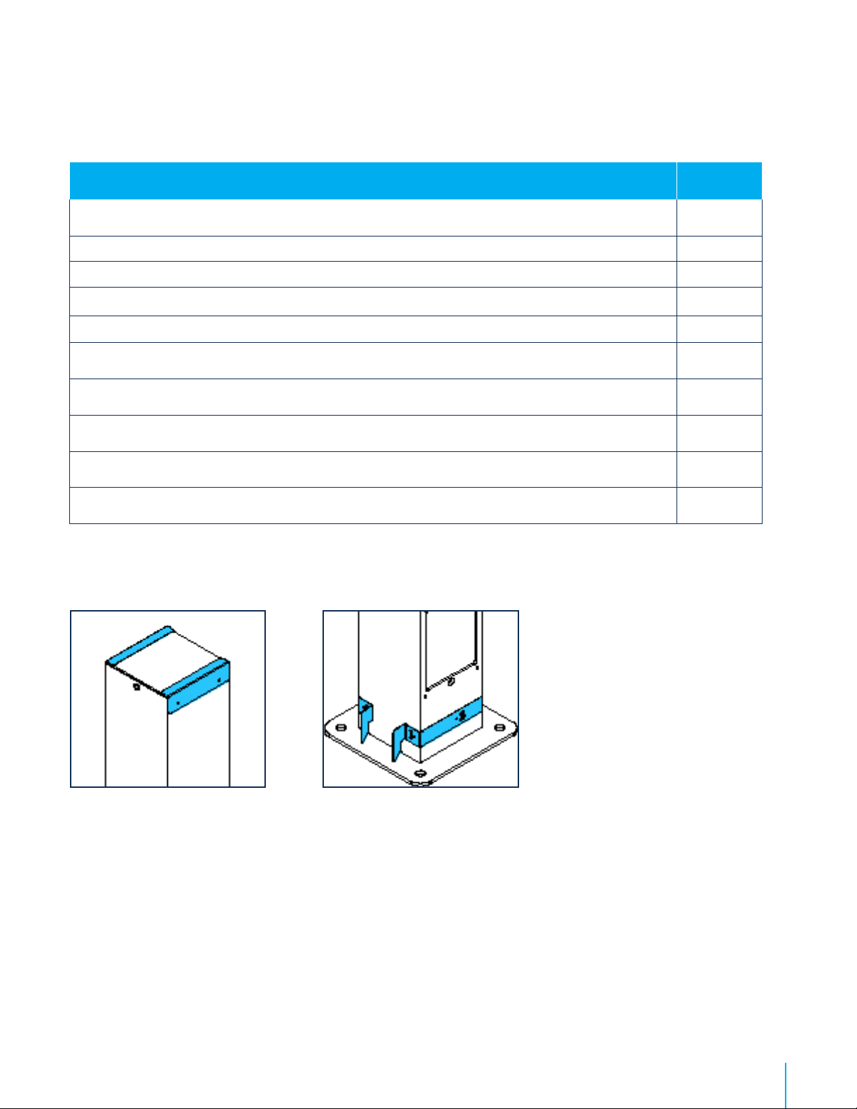
1. Install the rectangular spacing shim, place the column
and than install the upper mount bracket on top.
Screw parts loosely with ¼-20 or self-drilling screws,
depending on the type of pedestal you have, so the
Cable management system column is maintained in
place and moves freely to install the lower mounting
hardware.
Recommendation : To position the column, when
standing in front of the charging station, make sure to
place the output of the Cable management on the exterior
side.
2. Screw the column of the Cable management system
by placing the round spacing shim (circled in red in
the image included) between the pedestal and the
column, and tighten the screws to solidly secure the
column.
3. Secure the top bracket.
4. Install the empty column on the opposite side of the
charging station by following the above steps 1 to 3.
5. Proceed with the positioning of the cable clamp. Refer
to page 15.
6. Install the poster panel. Refer to page 16.
Caution : This pedestal is certied like an electrical enclosure,
and any alteration must comply with local regulation.

CoRe+TM
Cable management system and pedestal installation guide
10
Dual back-to-back charging
station installation
IF THE PEDESTAL IS NOT PRE-DRILLED, USE THE FOLLOWING DRILLING TEMPLATES:
Top Drilling template
MEC-CST-00280
Bottom Drilling template
MEC-CST-00278
Included material Qty
Cable management system columns and cable clamp 2
Top mounting brackets 2
Round spacing shims 2
Rectangular spacing shims 2
Self-adhesive rubber band 2
¼-20 screws (1’’) (for pre-drilled pedestal) 6
Self-drilling screws (1’’) (for pedestal with no holes) 6
Drilling template 1
Drilling template (bottom pedestal)1
Otros manuales para CoRe+
5
Este manual sirve para los siguientes modelos
1
Tabla de contenidos
Otros manuales de Cargador de baterías de Flo


